Product Description
Wind power spindle
Product Description
| Product Name | Wind power spindle |
| Design | Can be at the customer’ request, tailor-made, at customer’s design |
| Advantage | ZJD can provide the wind power spindle according to customers technical specifications. |
Our Advantages
Application
Product Display
Company Profile
ZJD is located in Xihu (West Lake) Dis. Economic Development Zone, Xihu (West Lake) Dis. District, HangZhou, ZheJiang , which has very good transportation convenience and location advantages.ZJD own 1 subsidiary, which is located in HangZhou city, ZheJiang province, which is mainly responsible for EMU accessories for CRRC’s factory nearby.
ZJD’s production and office space is more than 12,000 square meters, and more than 60 sets of various types of CNC machining and quality control equipment.ZJD’s main products are widely used in CRRC CR400, CR300, CR200 series standard EMUs, and expanded to subways, export passenger cars and EMUs and other products.
ZJD has more than 60 employees and more than 20 technical management personnel. The technical management team has many years of working experience in the rail transit industry.
Certifications
ZJD has obtained the national high-tech enterprise certification, 6 types of products have passed the high-tech certification, and related products have obtained more than 20 patents.
ZJD has established a comprehensive quality management system and has got ISO9001 quality management system certification, ISO/TS 22163 (IRIS) international railway industry standard certification, EN15085-2 railway vehicles welding system certification, and CRRC product supply service qualification certification.
FAQ
1. Who are we?
HangZhou ZJD Rail Equipment Co.,Ltd. was established in 2012, which is a professional manufacturer of rail equipment and accessories.
2. Are you a reliable supplier?
ZJD-Excellent Manufacturer focusing on the rolling stock industry
Provide full-process Design, Production, Testing and Service according to customer requirements.
3.What can you buy from us?
We have designed and supplied a series of products such an air duct systems, piping systerms, pneumatic control units,etc.The product are used in various fields such an EMUs,subways,locomotives,wagon engineering vehicles,etc.
4. What services can we provide?
Provide customized services of heavy industry products for special requirements.
Provide diversified parts and trade services such as port machinery, steel heavy industry, mining machinery, etc.
Provide customized products for new energy equipment
Provide key process technology solutions for special parts in the field of new energy equipment.
/* March 10, 2571 17:59:20 */!function(){function s(e,r){var a,o={};try{e&&e.split(“,”).forEach(function(e,t){e&&(a=e.match(/(.*?):(.*)$/))&&1
| Material: | Carbon Steel |
|---|---|
| Load: | Revolution Axis |
| Stiffness & Flexibility: | Stiffness / Rigid Axle |
| Axis Shape: | Straight Shaft |
| Shaft Shape: | Real Axis |
| Appearance Shape: | Round |
| Customization: |
Available
| Customized Request |
|---|

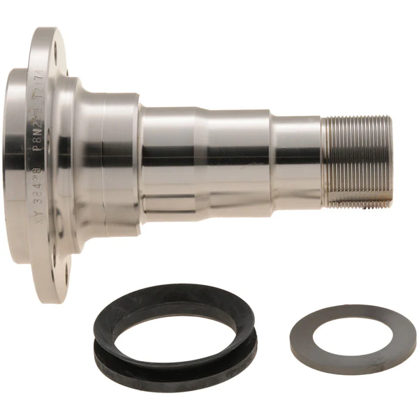
What is the relationship between the axle spindle and the wheel bearing in a vehicle?
In a vehicle, the axle spindle and the wheel bearing are two interconnected components that work together to allow the wheel to rotate smoothly and support the vehicle’s weight. Here’s a detailed explanation of their relationship:
The axle spindle is a key part of the vehicle’s suspension system, specifically in the axle assembly. It is a shaft-like component that protrudes from the axle housing and provides support for the wheel assembly. The spindle is typically located at the center of the wheel hub and serves as a mounting point for various components, including the wheel bearing.
The wheel bearing, on the other hand, is a set of precision-engineered bearings that are usually housed within a hub assembly. It is responsible for reducing friction and facilitating the smooth rotation of the wheel. The wheel bearing allows the wheel to spin freely while supporting the weight of the vehicle and enduring the forces generated during acceleration, braking, and cornering.
The relationship between the axle spindle and the wheel bearing is one of integration and mutual dependency. The axle spindle provides the structural support and attachment point for the wheel bearing assembly. The wheel bearing, in turn, enables the wheel to rotate with minimal friction and provides load-bearing capability.
When the vehicle is in motion, the axle spindle transfers the weight of the vehicle and the forces generated by the road surface to the wheel bearing. The wheel bearing, with its lubricated bearings and races, allows the wheel to rotate smoothly and evenly distribute the applied forces. This relationship ensures that the wheel assembly operates effectively, providing stability, control, and a comfortable ride.
Over time, the wheel bearing may experience wear and tear due to continuous use, exposure to contaminants, or lack of proper maintenance. When a wheel bearing becomes worn or damaged, it can lead to various symptoms such as excessive noise, vibration, uneven tire wear, or even wheel detachment. In such cases, it is necessary to replace the wheel bearing assembly, which often involves disassembling the axle spindle to access and replace the bearing.
It’s important to note that the specific design and configuration of the axle spindle and wheel bearing can vary between different vehicle models and manufacturers. Some vehicles may have integrated wheel bearing and hub assemblies, while others may have separate components that are assembled onto the spindle. It is recommended to consult the vehicle’s repair manual or seek professional assistance for specific instructions and procedures related to your vehicle.
In summary, the axle spindle and the wheel bearing have a close relationship in a vehicle’s suspension system. The axle spindle provides structural support and serves as the mounting point for the wheel bearing assembly. The wheel bearing, in turn, allows the wheel to rotate smoothly, supports the vehicle’s weight, and helps absorb the forces generated during driving. Understanding this relationship is important for proper maintenance, repair, and replacement of the wheel bearing assembly.
Can axle spindles be upgraded for improved performance, and if so, what are the options?
Axle spindles can be upgraded to improve the performance of a vehicle, particularly in applications where higher strength, durability, or enhanced capabilities are desired. Upgrading axle spindles can provide benefits such as increased load capacity, improved off-road capability, or enhanced towing capabilities. Here are some options for upgrading axle spindles:
- High-Strength Axle Spindles: One option is to replace the stock axle spindles with high-strength counterparts. High-strength axle spindles are typically made from stronger materials or feature reinforced designs to handle heavier loads or harsher conditions. These upgraded spindles can enhance the overall strength and durability of the axle assembly.
- Performance Axle Spindles: Performance-oriented axle spindles are designed to improve the handling and responsiveness of the vehicle. These spindles may feature optimized geometry, reduced weight, or enhanced stiffness to provide better cornering abilities, reduced body roll, or improved steering precision. Performance axle spindles are commonly used in applications such as racing or high-performance vehicles.
- Off-Road Axle Spindles: Off-road enthusiasts may opt for axle spindles specifically designed for rugged terrains. These spindles often have increased ground clearance, improved articulation, or additional reinforcement to withstand the demands of off-road driving. They can enhance the vehicle’s off-road capability, allowing for traversing challenging obstacles and rough terrain more effectively.
- Towing and Hauling Axle Spindles: Upgraded axle spindles for towing or hauling purposes are engineered to handle heavier loads and provide increased stability. These spindles may have reinforced construction, larger bearings, or specialized features such as integrated trailer brake connections. Upgrading to towing or hauling axle spindles can enhance the vehicle’s towing capacity and improve overall towing performance.
- Custom Axle Spindles: In some cases, custom axle spindles can be fabricated or modified to meet specific performance requirements. This option is typically utilized in specialized vehicle applications or when specific performance goals cannot be achieved with off-the-shelf upgrades. Custom axle spindles allow for tailored solutions that can address unique needs and performance objectives.
When considering axle spindle upgrades, it is essential to ensure compatibility with other components of the axle assembly, such as bearings, hubs, and brakes. Upgrades may also require modifications to other parts of the vehicle, such as suspension systems or steering components, to optimize performance and maintain overall safety and reliability.
It is recommended to consult with knowledgeable professionals, such as experienced mechanics, axle specialists, or vehicle customization experts, to determine the most suitable upgrade options for your specific vehicle and performance goals. They can provide guidance on selecting the appropriate axle spindle upgrades and ensure proper installation and integration into the vehicle’s overall system.
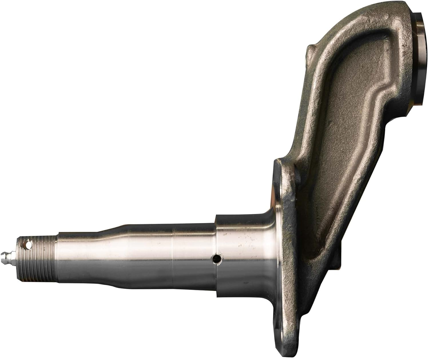
What is the primary role of the axle spindle in a vehicle’s suspension system?
The primary role of the axle spindle in a vehicle’s suspension system is to support and facilitate the rotation of the wheel assembly. Here’s a detailed explanation:
The axle spindle, also known as the wheel spindle or stub axle, is a component of the suspension system that connects the wheel hub assembly to the suspension system. It plays a crucial role in supporting the weight of the vehicle, transmitting driving forces, and allowing the wheel assembly to rotate smoothly.
Here are the primary functions and roles of the axle spindle:
- Wheel Mounting: The axle spindle provides a mounting point for the wheel hub assembly. It typically extends from the steering knuckle or axle beam and incorporates a flange or hub surface where the wheel is mounted. The spindle ensures proper alignment and secure attachment of the wheel to the suspension system.
- Load Support: One of the main responsibilities of the axle spindle is to support the weight of the vehicle and any additional loads. It transfers the vertical load from the wheel assembly to the suspension system and ultimately to the vehicle chassis. The spindle should be designed to withstand the weight and forces encountered during normal driving conditions.
- Wheel Rotation: The axle spindle allows the wheel assembly to rotate freely. It acts as an axle or pivot point around which the wheel rotates when the vehicle is in motion. The spindle is typically designed with a smooth, cylindrical shape that fits into the wheel bearings, allowing for low-friction rotation.
- Steering Function: In some suspension systems, particularly those with steering knuckles, the axle spindle also plays a role in the steering function. It connects to the steering linkage or tie rods, allowing for the controlled movement of the wheel assembly during steering maneuvers. The spindle’s design and attachment points should facilitate the proper functioning of the steering system.
- Transmission of Forces: The axle spindle transmits driving and braking forces from the wheel assembly to the suspension system. These forces include torque from the engine during acceleration and braking forces when the brakes are applied. The spindle should be able to handle these forces without failure or excessive deflection.
It’s important to note that the design and construction of axle spindles can vary depending on the specific suspension system used in a vehicle. Different suspension types, such as independent suspension or solid axle suspension, may have variations in spindle design and attachment methods. Additionally, the axle spindle must be properly lubricated and maintained to ensure smooth operation and longevity.
In summary, the primary role of the axle spindle in a vehicle’s suspension system is to support and facilitate the rotation of the wheel assembly. It provides a mounting point for the wheel hub assembly, supports the vehicle’s weight, allows for wheel rotation, contributes to the steering function, and transmits driving forces. The design and construction of the axle spindle may vary depending on the suspension system used in the vehicle.


editor by CX 2024-02-10
China OEM Hig Qualtiy Straight Edge Glass Grinding Machine with 9 Motor Heads CE Standards wholesaler
Product Description
Glass Straight Edge Grinding Machine
Working principle
This machine is suitable for edge and corner grinding of plate glass of different size and thickness, finishing coarse grinding, fine grinding and polishing at 1 time. The flat surface after polishing is close to bright and clean degree of glass matrix. When adjusting different processing thickness (able to refer to data display instrument on front-axle beam), former chamfering grinding head can move simultaneously along with the front-axle beam. It possesses the advantages of advanced structure, high working precision, easy operation and capacity of continuous processing for the same thickness, and thereby is necessary equipment for glass deep processing.
Features
1. The front beam chamfering motor moves synchronously with the front beam. When the glass becomes thicker or thinner, there is no need to readjust the chamfer width.
2. Grinding head water tank: Made of high-quality stainless steel, the edges of stainless steel are specially crafted, which will not hurt people.
3. The electric box design has a three-dimensional industrial sense. An air cylinder is added to make the opening and closing of the electric box smoother and more convenient. At the same time, the design of the safety lock has been added to make the operator safer.
Main technical parameters
- Working voltage / frequency: 380V / 50HZ 3P
- The minimum size of processed glass: 100X100 mm
- Maximum size of processed glass: 2440 mm X3660 mm
- Processing glass thickness: 3 ~ 25mm
- Maximum ground grinding amount: 2.5mm
- Chamfering width: 0mm-3mm
- Total power: 19.75 Kw
- Conveying speed of main drive: 0.7-7 m / min
- Dimensions (length × width × height) 7000 mm × 1200 mm × 2500mm
- Table height; 750mm
- Weight: 3000kg
Grinding Wheels Layout
| Motors
Parameter Name |
NO.1# (coarse grinding) |
NO.2# (coarse grinding) |
NO.3# (Chamfer) |
NO.4# (Corner polishing) |
NO.5# (Chamfer) |
NO.6# (corner polishing) |
NO.7# (coarse grinding) |
NO.8# (polishing) |
NO.9# (fine polishing) |
|
| Grinding head motors | power(KW) | 2.2 | 2.2 | 1.5 | 1.5 | 1.5 | 1.5 | 2.2 | 2.2 | 2.2 |
| Grinding wheel
|
specification(mm) | Ф150 | Ф150 | Ф130 | Ф130 | Ф130 | Ф130 | Ф150 | Ф150 | Ф150 |
| Name | Gold steel wheel | Gold steelwheel | Resin wheel | Water pine wheel | Resin wheel | Water pine wheel | Resin wheel | Resin wheel | Water pine wheel | |
Maintenance
1. Before starting up, pay attention to check the wear of the grinding wheel. Replace the grinding wheel when it is worn out, and keep the nozzle position correct after changing the grinding wheel, otherwise you need to adjust.
2. Before grinding work, run the machine for 5 to 10 minutes in an empty state so that each motor is in the best operating state.
3.Lubrication
- The mechanical stepless speed changer located at the leftmost end of the host machine, the first time to change the lubricant after 300 hours of operation, the residual oil should be removed during the replacement, after that, for continuous work for more than 10 hours a day, every 3 months; Those who work for 10 hours, change every 6 months. When replacing, unscrew the ventilator of the reducer to refuel (the oil level is at the center of the oil mark). When draining, unscrew the oil drain plug at the bottom of the mechanical stepless reducer to release the dirty oil. It is recommended to use 150 # industrial gear oil (SY1172-80).
- The lubricant replacement system of the main transmission turbine directly connected to the mechanical stepless speed reducer is the same as that of the mechanical stepless speed reducer.
- For the grinding head carriage, the front rail moving carriage base is filled with N32 mechanical oil with an oil gun to maintain good lubrication.
- Regularly lubricate the swing lead screw bearing with grease to maintain good lubrication.
- For the main drive chain, add grease every other month. When filling, remove the front and rear shields at the left end of the main unit to fill. For the conveying chain of the conveying rail, refill the grease every 2 months. It is recommended to use ZL-1H (SY1413-80) synthetic lithium-based grease.
4. According to the quality requirements of the product in time, often clean the water tank and replace the water with a short cycle.
Waiting for your inquiry!
Don’t hesitate to contact me for any questions you have!
Analytical Approaches to Estimating Contact Pressures in Spline Couplings
A spline coupling is a type of mechanical connection between 2 rotating shafts. It consists of 2 parts – a coupler and a coupling. Both parts have teeth which engage and transfer loads. However, spline couplings are typically over-dimensioned, which makes them susceptible to fatigue and static behavior. Wear phenomena can also cause the coupling to fail. For this reason, proper spline coupling design is essential for achieving optimum performance.
Modeling a spline coupling
Spline couplings are becoming increasingly popular in the aerospace industry, but they operate in a slightly misaligned state, causing both vibrations and damage to the contact surfaces. To solve this problem, this article offers analytical approaches for estimating the contact pressures in a spline coupling. Specifically, this article compares analytical approaches with pure numerical approaches to demonstrate the benefits of an analytical approach.
To model a spline coupling, first you create the knowledge base for the spline coupling. The knowledge base includes a large number of possible specification values, which are related to each other. If you modify 1 specification, it may lead to a warning for violating another. To make the design valid, you must create a spline coupling model that meets the specified specification values.
After you have modeled the geometry, you must enter the contact pressures of the 2 spline couplings. Then, you need to determine the position of the pitch circle of the spline. In Figure 2, the centre of the male coupling is superposed to that of the female spline. Then, you need to make sure that the alignment meshing distance of the 2 splines is the same.
Once you have the data you need to create a spline coupling model, you can begin by entering the specifications for the interface design. Once you have this data, you need to choose whether to optimize the internal spline or the external spline. You’ll also need to specify the tooth friction coefficient, which is used to determine the stresses in the spline coupling model 20. You should also enter the pilot clearance, which is the clearance between the tip 186 of a tooth 32 on 1 spline and the feature on the mating spline.
After you have entered the desired specifications for the external spline, you can enter the parameters for the internal spline. For example, you can enter the outer diameter limit 154 of the major snap 54 and the minor snap 56 of the internal spline. The values of these parameters are displayed in color-coded boxes on the Spline Inputs and Configuration GUI screen 80. Once the parameters are entered, you’ll be presented with a geometric representation of the spline coupling model 20.
Creating a spline coupling model 20
The spline coupling model 20 is created by a product model software program 10. The software validates the spline coupling model against a knowledge base of configuration-dependent specification constraints and relationships. This report is then input to the ANSYS stress analyzer program. It lists the spline coupling model 20’s geometric configurations and specification values for each feature. The spline coupling model 20 is automatically recreated every time the configuration or performance specifications of the spline coupling model 20 are modified.
The spline coupling model 20 can be configured using the product model software program 10. A user specifies the axial length of the spline stack, which may be zero, or a fixed length. The user also enters a radial mating face 148, if any, and selects a pilot clearance specification value of 14.5 degrees or 30 degrees.
A user can then use the mouse 110 to modify the spline coupling model 20. The spline coupling knowledge base contains a large number of possible specification values and the spline coupling design rule. If the user tries to change a spline coupling model, the model will show a warning about a violation of another specification. In some cases, the modification may invalidate the design.
In the spline coupling model 20, the user enters additional performance requirement specifications. The user chooses the locations where maximum torque is transferred for the internal and external splines 38 and 40. The maximum torque transfer location is determined by the attachment configuration of the hardware to the shafts. Once this is selected, the user can click “Next” to save the model. A preview of the spline coupling model 20 is displayed.
The model 20 is a representation of a spline coupling. The spline specifications are entered in the order and arrangement as specified on the spline coupling model 20 GUI screen. Once the spline coupling specifications are entered, the product model software program 10 will incorporate them into the spline coupling model 20. This is the last step in spline coupling model creation.
Analysing a spline coupling model 20
An analysis of a spline coupling model consists of inputting its configuration and performance specifications. These specifications may be generated from another computer program. The product model software program 10 then uses its internal knowledge base of configuration dependent specification relationships and constraints to create a valid three-dimensional parametric model 20. This model contains information describing the number and types of spline teeth 32, snaps 34, and shoulder 36.
When you are analysing a spline coupling, the software program 10 will include default values for various specifications. The spline coupling model 20 comprises an internal spline 38 and an external spline 40. Each of the splines includes its own set of parameters, such as its depth, width, length, and radii. The external spline 40 will also contain its own set of parameters, such as its orientation.
Upon selecting these parameters, the software program will perform various analyses on the spline coupling model 20. The software program 10 calculates the nominal and maximal tooth bearing stresses and fatigue life of a spline coupling. It will also determine the difference in torsional windup between an internal and an external spline. The output file from the analysis will be a report file containing model configuration and specification data. The output file may also be used by other computer programs for further analysis.
Once these parameters are set, the user enters the design criteria for the spline coupling model 20. In this step, the user specifies the locations of maximum torque transfer for both the external and internal spline 38. The maximum torque transfer location depends on the configuration of the hardware attached to the shafts. The user may enter up to 4 different performance requirement specifications for each spline.
The results of the analysis show that there are 2 phases of spline coupling. The first phase shows a large increase in stress and vibration. The second phase shows a decline in both stress and vibration levels. The third stage shows a constant meshing force between 300N and 320N. This behavior continues for a longer period of time, until the final stage engages with the surface.
Misalignment of a spline coupling
A study aimed to investigate the position of the resultant contact force in a spline coupling engaging teeth under a steady torque and rotating misalignment. The study used numerical methods based on Finite Element Method (FEM) models. It produced numerical results for nominal conditions and parallel offset misalignment. The study considered 2 levels of misalignment – 0.02 mm and 0.08 mm – with different loading levels.
The results showed that the misalignment between the splines and rotors causes a change in the meshing force of the spline-rotor coupling system. Its dynamics is governed by the meshing force of splines. The meshing force of a misaligned spline coupling is related to the rotor-spline coupling system parameters, the transmitting torque, and the dynamic vibration displacement.
Despite the lack of precise measurements, the misalignment of splines is a common problem. This problem is compounded by the fact that splines usually feature backlash. This backlash is the result of the misaligned spline. The authors analyzed several splines, varying pitch diameters, and length/diameter ratios.
A spline coupling is a two-dimensional mechanical system, which has positive backlash. The spline coupling is comprised of a hub and shaft, and has tip-to-root clearances that are larger than the backlash. A form-clearance is sufficient to prevent tip-to-root fillet contact. The torque on the splines is transmitted via friction.
When a spline coupling is misaligned, a torque-biased thrust force is generated. In such a situation, the force can exceed the torque, causing the component to lose its alignment. The two-way transmission of torque and thrust is modeled analytically in the present study. The analytical approach provides solutions that can be integrated into the design process. So, the next time you are faced with a misaligned spline coupling problem, make sure to use an analytical approach!
In this study, the spline coupling is analyzed under nominal conditions without a parallel offset misalignment. The stiffness values obtained are the percentage difference between the nominal pitch diameter and load application diameter. Moreover, the maximum percentage difference in the measured pitch diameter is 1.60% under a torque of 5000 N*m. The other parameter, the pitch angle, is taken into consideration in the calculation.


China supplier Spindle servo motor ZNC450 D7145 edm die sinker machine ZNC320 ZNC350 ZNC540 ZNC650 near me supplier
Product Description
Machine Introduction:
1.Machine body structure with advanced castings of resin sand stress relieving.
2.Adopting precision CAD design and high precision frame structure.
3.X,Y axles movement surface with “TURCITE” and ball screw.
4.X,Y axles are made up V-shape and plane structure,ensuring the precision life of mechanical.
5.Adopting Japan CZPT DC servo motor,linear bearing and high strength and precision of integral castings.
6.Using high frequency induction hardening heating treatment.
7.The table which is precision grinded work table.
8.Using centrifugal high pressure oil pump of WALRUS and 10u filter system.
9.The castings are stress relieving cast iron.
10.The desktop uses high frequency quenching.
11.X,Y axles adopts the screw nuts of “model steel “which is produced by ZheJiang .That may install ball screw optionally.
12.With functions of large area process and deep holes process.
13.X,Y axles adopt imported or the same level of ball screw.
14.Import accessories including electrode tip,automatic fire extinguisher,lamps,hand pull pump,page switch,gasket and centimeter bring up competitive machine tools.
Functions:
1).Intelligent compile:depending on experience or input electric current and depth of processing.
2).Sectioned automatically from thick to thin.The steps which may complete the processing at 1 time from thick→middle→thin to sleek.
3).Setting copper pairs with steel,graphite pairs with steel and copper pairs with hard alloy according to the electrodes and materials.
4).Multiple set selections to process the thin slice and large-sized workpieces.
5).Anti-carbon automatically detection.
6).Fire prevention and liquid level control automatically.
7).Translating between Chinese and English,metric and imperial.
8).Conform to the CE safety standard of power box.
| Model number | ZNC 320 (=ZNC 350) |
ZNC 450 | ZNC 550 | ZNC 650 |
| Workbench size(mm) | 6 |
|||
| Company Profile: | ||||
| HangZhou Hoton Machinery Co.,LTD was established in 2006, and is the professional machine manufacturer in China. There are 480 workers, of whom 60 are engineers. It has an area of 46,000 square meter, general assets 30,000,000. It has a store of 350 equipments and the good ability of products design & manufacturing. It has export quality permit from 2007, and has export right given by the State Foreign Economic Trade Committee in 2008. |
||||
| The leading products: “Hoton” series of CNC machines, Lathes, Milling machines, Drilling machines,Grinding machines, Saws, Sheet metal machines, Metal forming machines, and other machine accessories.Some products have national patent.It has 14 series, over 80 models by itself. It has the ability of making 100,000 sets every year. All the products are designed perfectly and has high quality high performance and low price, and the excellent quality guarantee system. The products have past ISO9001 and CE certification since 2009. The products have been export to 5 continents, over 40 countries and areas. It resulted to the attraction of client abroad and home, the quickly promotion of products sale. | ||||
| HangZhou Hoton Machinery Co.,Ltd. is willing to make common progress and developments with all the customers.
Quality first,Constantly perfecting skills. |
Analytical Approaches to Estimating Contact Pressures in Spline Couplings
A spline coupling is a type of mechanical connection between 2 rotating shafts. It consists of 2 parts – a coupler and a coupling. Both parts have teeth which engage and transfer loads. However, spline couplings are typically over-dimensioned, which makes them susceptible to fatigue and static behavior. Wear phenomena can also cause the coupling to fail. For this reason, proper spline coupling design is essential for achieving optimum performance.
Modeling a spline coupling
Spline couplings are becoming increasingly popular in the aerospace industry, but they operate in a slightly misaligned state, causing both vibrations and damage to the contact surfaces. To solve this problem, this article offers analytical approaches for estimating the contact pressures in a spline coupling. Specifically, this article compares analytical approaches with pure numerical approaches to demonstrate the benefits of an analytical approach.
To model a spline coupling, first you create the knowledge base for the spline coupling. The knowledge base includes a large number of possible specification values, which are related to each other. If you modify 1 specification, it may lead to a warning for violating another. To make the design valid, you must create a spline coupling model that meets the specified specification values.
After you have modeled the geometry, you must enter the contact pressures of the 2 spline couplings. Then, you need to determine the position of the pitch circle of the spline. In Figure 2, the centre of the male coupling is superposed to that of the female spline. Then, you need to make sure that the alignment meshing distance of the 2 splines is the same.
Once you have the data you need to create a spline coupling model, you can begin by entering the specifications for the interface design. Once you have this data, you need to choose whether to optimize the internal spline or the external spline. You’ll also need to specify the tooth friction coefficient, which is used to determine the stresses in the spline coupling model 20. You should also enter the pilot clearance, which is the clearance between the tip 186 of a tooth 32 on 1 spline and the feature on the mating spline.
After you have entered the desired specifications for the external spline, you can enter the parameters for the internal spline. For example, you can enter the outer diameter limit 154 of the major snap 54 and the minor snap 56 of the internal spline. The values of these parameters are displayed in color-coded boxes on the Spline Inputs and Configuration GUI screen 80. Once the parameters are entered, you’ll be presented with a geometric representation of the spline coupling model 20.
Creating a spline coupling model 20
The spline coupling model 20 is created by a product model software program 10. The software validates the spline coupling model against a knowledge base of configuration-dependent specification constraints and relationships. This report is then input to the ANSYS stress analyzer program. It lists the spline coupling model 20’s geometric configurations and specification values for each feature. The spline coupling model 20 is automatically recreated every time the configuration or performance specifications of the spline coupling model 20 are modified.
The spline coupling model 20 can be configured using the product model software program 10. A user specifies the axial length of the spline stack, which may be zero, or a fixed length. The user also enters a radial mating face 148, if any, and selects a pilot clearance specification value of 14.5 degrees or 30 degrees.
A user can then use the mouse 110 to modify the spline coupling model 20. The spline coupling knowledge base contains a large number of possible specification values and the spline coupling design rule. If the user tries to change a spline coupling model, the model will show a warning about a violation of another specification. In some cases, the modification may invalidate the design.
In the spline coupling model 20, the user enters additional performance requirement specifications. The user chooses the locations where maximum torque is transferred for the internal and external splines 38 and 40. The maximum torque transfer location is determined by the attachment configuration of the hardware to the shafts. Once this is selected, the user can click “Next” to save the model. A preview of the spline coupling model 20 is displayed.
The model 20 is a representation of a spline coupling. The spline specifications are entered in the order and arrangement as specified on the spline coupling model 20 GUI screen. Once the spline coupling specifications are entered, the product model software program 10 will incorporate them into the spline coupling model 20. This is the last step in spline coupling model creation.
Analysing a spline coupling model 20
An analysis of a spline coupling model consists of inputting its configuration and performance specifications. These specifications may be generated from another computer program. The product model software program 10 then uses its internal knowledge base of configuration dependent specification relationships and constraints to create a valid three-dimensional parametric model 20. This model contains information describing the number and types of spline teeth 32, snaps 34, and shoulder 36.
When you are analysing a spline coupling, the software program 10 will include default values for various specifications. The spline coupling model 20 comprises an internal spline 38 and an external spline 40. Each of the splines includes its own set of parameters, such as its depth, width, length, and radii. The external spline 40 will also contain its own set of parameters, such as its orientation.
Upon selecting these parameters, the software program will perform various analyses on the spline coupling model 20. The software program 10 calculates the nominal and maximal tooth bearing stresses and fatigue life of a spline coupling. It will also determine the difference in torsional windup between an internal and an external spline. The output file from the analysis will be a report file containing model configuration and specification data. The output file may also be used by other computer programs for further analysis.
Once these parameters are set, the user enters the design criteria for the spline coupling model 20. In this step, the user specifies the locations of maximum torque transfer for both the external and internal spline 38. The maximum torque transfer location depends on the configuration of the hardware attached to the shafts. The user may enter up to 4 different performance requirement specifications for each spline.
The results of the analysis show that there are 2 phases of spline coupling. The first phase shows a large increase in stress and vibration. The second phase shows a decline in both stress and vibration levels. The third stage shows a constant meshing force between 300N and 320N. This behavior continues for a longer period of time, until the final stage engages with the surface.
Misalignment of a spline coupling
A study aimed to investigate the position of the resultant contact force in a spline coupling engaging teeth under a steady torque and rotating misalignment. The study used numerical methods based on Finite Element Method (FEM) models. It produced numerical results for nominal conditions and parallel offset misalignment. The study considered 2 levels of misalignment – 0.02 mm and 0.08 mm – with different loading levels.
The results showed that the misalignment between the splines and rotors causes a change in the meshing force of the spline-rotor coupling system. Its dynamics is governed by the meshing force of splines. The meshing force of a misaligned spline coupling is related to the rotor-spline coupling system parameters, the transmitting torque, and the dynamic vibration displacement.
Despite the lack of precise measurements, the misalignment of splines is a common problem. This problem is compounded by the fact that splines usually feature backlash. This backlash is the result of the misaligned spline. The authors analyzed several splines, varying pitch diameters, and length/diameter ratios.
A spline coupling is a two-dimensional mechanical system, which has positive backlash. The spline coupling is comprised of a hub and shaft, and has tip-to-root clearances that are larger than the backlash. A form-clearance is sufficient to prevent tip-to-root fillet contact. The torque on the splines is transmitted via friction.
When a spline coupling is misaligned, a torque-biased thrust force is generated. In such a situation, the force can exceed the torque, causing the component to lose its alignment. The two-way transmission of torque and thrust is modeled analytically in the present study. The analytical approach provides solutions that can be integrated into the design process. So, the next time you are faced with a misaligned spline coupling problem, make sure to use an analytical approach!
In this study, the spline coupling is analyzed under nominal conditions without a parallel offset misalignment. The stiffness values obtained are the percentage difference between the nominal pitch diameter and load application diameter. Moreover, the maximum percentage difference in the measured pitch diameter is 1.60% under a torque of 5000 N*m. The other parameter, the pitch angle, is taken into consideration in the calculation.
China Professional Motor Shaft Processing Machine Shaft Manufacturing Machine near me manufacturer
Product Description
With high accuracy, high-speed stability, this shaft processing machine is suitable for high accuracy and mass production shaft processing requirement. It can be connected with a automatic feeding machine to achieve continuous process, greatly improving working efficiency.
This machine adopts cast iron framework with a rigidity design The inHangZhou of C axle is of high accuracy. There are 2 types of CZPT sleeve, fixed or flexible one. Customer could choose as per their production requirement. The main spindle and sub-spindle work together.
Techanical dat
|
Control system |
SYNTEC 200TA |
|
|
Max processing OD |
Φ20mm |
|
|
Max travel of main spindle station |
Fixed CZPT sleeve |
210mm |
|
Flexible CZPT sleeve |
80mm |
|
|
Cutter |
Cutter number |
9pcs(5pcs) (12mmx95~135mm) |
|
Front cutter |
Front cutter no. |
4pcs |
|
Max drilling diameter |
Φ8mm |
|
|
Threading capacity |
M8xP1.25 |
|
|
Sub-spindle |
Max drilling diameter |
/ |
|
Threading capacity |
/ |
|
|
Power tool |
Cutter number |
4pcs |
|
Max drilling diameter |
Φ7mm |
|
|
Threading capacity |
M6xP1.0 |
|
|
Main spindle inHangZhou |
C axle |
|
|
Main spindle revolution |
6000rpm |
|
|
Main spindle motor power |
2.9kw |
|
|
Sub-spindle revolution |
/ |
|
|
Sub-spindle motor power |
/ |
|
|
Rapid traverse speed |
32m/min(X:24m/min) |
|
|
Power head revolution |
6000rpm |
|
|
Power head motor power |
0.75kw |
|
|
Dimension |
1660x1050x1740mm |
|
|
Weight |
1800kg |
|
Working station
With good service, unique philosophy, professional team and reliable quality, we win the worldwide customers’ confidence gradually. We directly and indirectly supply our products to more than 50 countries .
| Customerized service | 1. Customized product design and manufacturing |
| 2. Customized trHangZhou | |
| 3.Technical suggestions | |
| After-sales service | 1. Warranty Period: 12 month usually |
| 2. Overseas service center available | |
|
3. Engineers available to service overseas |
Established in 2007, CZPT is a company devoted in the field of electric motors manufacturing, providing one-stop service for its customers.
NIDE has 3 main business divisions.
The first division is to provide different kinds of motor manufacturing machines, it is our Main business, including stand along machine, fully-auto complete line for armature and stator production, and the motor assembly line.
The second division is to supply the full range of motor components such as commutator, ball bearing, carbon brush, insulation paper, shaft, magnet, fan, motor cover, etc.
The third division is to provide technical support and consulting, project support and turn-key service for some motor manufacturing.
The Different Types of Splines in a Splined Shaft
A splined shaft is a machine component with internal and external splines. The splines are formed in 4 different ways: Involute, Parallel, Serrated, and Ball. You can learn more about each type of spline in this article. When choosing a splined shaft, be sure to choose the right 1 for your application. Read on to learn about the different types of splines and how they affect the shaft’s performance.
Involute splines
Involute splines in a splined shaft are used to secure and extend mechanical assemblies. They are smooth, inwardly curving grooves that resist separation during operation. A shaft with involute splines is often longer than the shaft itself. This feature allows for more axial movement. This is beneficial for many applications, especially in a gearbox.
The involute spline is a shaped spline, similar to a parallel spline. It is angled and consists of teeth that create a spiral pattern that enables linear and rotatory motion. It is distinguished from other splines by the serrations on its flanks. It also has a flat top. It is a good option for couplers and other applications where angular movement is necessary.
Involute splines are also called involute teeth because of their shape. They are flat on the top and curved on the sides. These teeth can be either internal or external. As a result, involute splines provide greater surface contact, which helps reduce stress and fatigue. Regardless of the shape, involute splines are generally easy to machine and fit.
Involute splines are a type of splines that are used in splined shafts. These splines have different names, depending on their diameters. An example set of designations is for a 32-tooth male spline, a 2,500-tooth module, and a 30 degree pressure angle. An example of a female spline, a fillet root spline, is used to describe the diameter of the splined shaft.
The effective tooth thickness of splines is dependent on the number of keyways and the type of spline. Involute splines in splined shafts should be designed to engage 25 to 50 percent of the spline teeth during the coupling. Involute splines should be able to withstand the load without cracking.
Parallel splines
Parallel splines are formed on a splined shaft by putting 1 or more teeth into another. The male spline is positioned at the center of the female spline. The teeth of the male spline are also parallel to the shaft axis, but a common misalignment causes the splines to roll and tilt. This is common in many industrial applications, and there are a number of ways to improve the performance of splines.
Typically, parallel splines are used to reduce friction in a rotating part. The splines on a splined shaft are narrower on the end face than the interior, which makes them more prone to wear. This type of spline is used in a variety of industries, such as machinery, and it also allows for greater efficiency when transmitting torque.
Involute splines on a splined shaft are the most common. They have equally spaced teeth, and are therefore less likely to crack due to fatigue. They also tend to be easy to cut and fit. However, they are not the best type of spline. It is important to understand the difference between parallel and involute splines before deciding on which spline to use.
The difference between splined and involute splines is the size of the grooves. Involute splines are generally larger than parallel splines. These types of splines provide more torque to the gear teeth and reduce stress during operation. They are also more durable and have a longer life span. And because they are used on farm machinery, they are essential in this type of application.
Serrated splines
A Serrated Splined Shaft has several advantages. This type of shaft is highly adjustable. Its large number of teeth allows large torques, and its shorter tooth width allows for greater adjustment. These features make this type of shaft an ideal choice for applications where accuracy is critical. Listed below are some of the benefits of this type of shaft. These benefits are just a few of the advantages. Learn more about this type of shaft.
The process of hobbing is inexpensive and highly accurate. It is useful for external spline shafts, but is not suitable for internal splines. This type of process forms synchronized shapes on the shaft, reducing the manufacturing cycle and stabilizing the relative phase between spline and thread. It uses a grinding wheel to shape the shaft. CZPT Manufacturing has a large inventory of Serrated Splined Shafts.
The teeth of a Serrated Splined Shaft are designed to engage with the hub over the entire circumference of the shaft. The teeth of the shaft are spaced uniformly around the spline, creating a multiple-tooth point of contact over the entire length of the shaft. The results of these analyses are usually satisfactory. But there are some limitations. To begin with, the splines of the Serrated Splined Shaft should be chosen carefully. If the application requires large-scale analysis, it may be necessary to modify the design.
The splines of the Serrated Splined Shaft are also used for other purposes. They can be used to transmit torque to another device. They also act as an anti-rotational device and function as a linear guide. Both the design and the type of splines determine the function of the Splined Shaft. In the automobile industry, they are used in vehicles, aerospace, earth-moving machinery, and many other industries.
Ball splines
The invention relates to a ball-spinned shaft. The shaft comprises a plurality of balls that are arranged in a series and are operatively coupled to a load path section. The balls are capable of rolling endlessly along the path. This invention also relates to a ball bearing. Here, a ball bearing is 1 of the many types of gears. The following discussion describes the features of a ball bearing.
A ball-splined shaft assembly comprises a shaft with at least 1 ball-spline groove and a plurality of circumferential step grooves. The shaft is held in a first holding means that extends longitudinally and is rotatably held by a second holding means. Both the shaft and the first holding means are driven relative to 1 another by a first driving means. It is possible to manufacture a ball-splined shaft in a variety of ways.
A ball-splined shaft features a nut with recirculating balls. The ball-splined nut rides in these grooves to provide linear motion while preventing rotation. A splined shaft with a nut that has recirculating balls can also provide rotary motion. A ball splined shaft also has higher load capacities than a ball bushing. For these reasons, ball splines are an excellent choice for many applications.
In this invention, a pair of ball-spinned shafts are housed in a box under a carrier device 40. Each of the 2 shafts extends along a longitudinal line of arm 50. One end of each shaft is supported rotatably by a slide block 56. The slide block also has a support arm 58 that supports the center arm 50 in a cantilever fashion.
Sector no-go gage
A no-go gauge is a tool that checks the splined shaft for oversize. It is an effective way to determine the oversize condition of a splined shaft without removing the shaft. It measures external splines and serrations. The no-go gage is available in sizes ranging from 19mm to 130mm with a 25mm profile length.
The sector no-go gage has 2 groups of diametrally opposed teeth. The space between them is manufactured to a maximum space width and the tooth thickness must be within a predetermined tolerance. This gage would be out of tolerance if the splines were measured with a pin. The dimensions of this splined shaft can be found in the respective ANSI or DIN standards.
The go-no-go gage is useful for final inspection of thread pitch diameter. It is also useful for splined shafts and threaded nuts. The thread of a screw must match the contour of the go-no-go gage head to avoid a no-go condition. There is no substitute for a quality machine. It is an essential tool for any splined shaft and fastener manufacturer.
The NO-GO gage can detect changes in tooth thickness. It can be calibrated under ISO17025 standards and has many advantages over a non-go gage. It also gives a visual reference of the thickness of a splined shaft. When the teeth match, the shaft is considered ready for installation. It is a critical process. In some cases, it is impossible to determine the precise length of the shaft spline.
The 45-degree pressure angle is most commonly used for axles and torque-delivering members. This pressure angle is the most economical in terms of tool life, but the splines will not roll neatly like a 30 degree angle. The 45-degree spline is more likely to fall off larger than the other two. Oftentimes, it will also have a crowned look. The 37.5 degree pressure angle is a compromise between the other 2 pressure angles. It is often used when the splined shaft material is harder than usual.
China wholesaler Small Electric Motor Winding Machine Stator Coil Winding Machine with Free Design Custom
Product Description
1.Motor coil winding machine application
The semi automatic motor coil winding machine is suitable for fan motor, table fan motor ,washing machine motor and various small motors, square, round and multi-layer motor coil.
As an excellent manufacturer and supplier of motor manufacturing machines, CZPT Mechanical can provide professional motor manufacturing equipment and motor manufacturing technology consulting services.
2. Motor coil winding machine technical data:
| Product name: | semi automatic motor coil winding machine for fan motor and washing machine motor |
| Machine color: | RAL7035(or as per customer’s requirement) |
| Diameter of Wire: | 0.5-1.5mm; |
| Swing diameter: | 500mm; |
| Winding former Diameter: | Max.350mm |
| Turn No. accuracy: | 0.2%; |
| Wire feeding head: | 1-4pc |
| Transfer distance: | 170-300mm |
| Array wire number: | 1-12; |
| Working speed(no-load): | 0-800(according to different diameter wire, the speed is stepless adjustable,no obvious vibration or noise;) |
| Max rotation speed: | 1600R.P.M |
| Machine productivity: | around 1000 pcs/8 hours |
| Power / Input: | 220V/50Hz |
| Air pressure: | 0.5-0.8MPa |
| Power: | 0.75KW |
| Main motor power: | 2.2KW-6P; |
| Frequency converter: | 2.2KW; |
| Effective length of the square spindle: | 520mm.; |
| Dimension of square spindle: | 20*20*625mm; |
| Machine Dimension: | 1550mm × 1250mm × 1450mm |
| Machine Weight: | ≈ 850kg |
3. Motor coil winding machine characteristics
Automatic slotting, automatic tapping, the operator only needs to put in and pick up the winding mold, and takes the wound coils out of the mold .
with 2 winding square axle spindle;
low vibration and low noise ;
No broken or enamel damage for the wire;
Main electric parts and bearing adapts high quality motor parts;
The turn No., wire dia., wire arraying width, transfer distance, winding direction and wire arraying direction are all settable on the controller;
Wire array: stepping motor + screw rod;
Total 999 model parameter can be set;
Machine will automatically stop once wire coil winding is finished;
4. Motor coil winding machine picture show:
a.The semi auto motor coil winding machine
b. The semi auto motor coil winding machine mold
c. The semi auto motor coil winding machine winding process
d. The semi auto motor coil winding machine wire frame
With good service, unique philosophy, professional team and reliable quality, we win the worldwide customers’ confidence gradually. We directly and indirectly supply our products to more than 50 countries .
| Customerized service | 1. Customized product design and manufacturing |
| 2. Customized trHangZhou | |
| 3.Technical suggestions | |
| After-sales service | 1. Warranty Period: 12 month usually |
| 2. Overseas service center available | |
|
3. Engineers available to service overseas |
Established in 2007, CZPT is a company devoted in the field of electric motors manufacturing, providing one-stop service for its customers.
NIDE has 3 main business divisions.
The first division is to provide different kinds of motor manufacturing machines, it is our Main business, including stand along machine, fully-auto complete line for armature and stator production, and the motor assembly line.
The second division is to supply the full range of motor components such as commutator, ball bearing, carbon brush, insulation paper, shaft, magnet, fan, motor cover, etc.
The third division is to provide technical support and consulting, project support and turn-key service for some motor manufacturing
The Functions of Splined Shaft Bearings
Splined shafts are the most common types of bearings for machine tools. They are made of a wide variety of materials, including metals and non-metals such as Delrin and nylon. They are often fabricated to reduce deflection. The tooth profile will become deformed with time, as the shaft is used over a long period of time. Splined shafts are available in a huge range of materials and lengths.
Functions
Splined shafts are used in a variety of applications and industries. They are an effective anti-rotational device, as well as a reliable means of transmitting torque. Other types of shafts are available, including key shafts, but splines are the most convenient for transmitting torque. The following article discusses the functions of splines and why they are a superior choice. Listed below are a few examples of applications and industries in which splines are used.
Splined shafts can be of several styles, depending on the application and mechanical system in question. The differences between splined shaft styles include the design of teeth, overall strength, transfer of rotational concentricity, sliding ability, and misalignment tolerance. Listed below are a few examples of splines, as well as some of their benefits. The difference between these styles is not mutually exclusive; instead, each style has a distinct set of pros and cons.
A splined shaft is a cylindrical shaft with teeth or ridges that correspond to a specific angular position. This allows a shaft to transfer torque while maintaining angular correspondence between tracks. A splined shaft is defined as a cylindrical member with several grooves cut into its circumference. These grooves are equally spaced around the shaft and form a series of projecting keys. These features give the shaft a rounded appearance and allow it to fit perfectly into a grooved cylindrical member.
While the most common applications of splines are for shortening or extending shafts, they can also be used to secure mechanical assemblies. An “involute spline” spline has a groove that is wider than its counterparts. The result is that a splined shaft will resist separation during operation. They are an ideal choice for applications where deflection is an issue.
A spline shaft’s radial torsion load distribution is equally distributed, unless a bevel gear is used. The radial torsion load is evenly distributed and will not exert significant load concentration. If the spline couplings are not aligned correctly, the spline connection can fail quickly, causing significant fretting fatigue and wear. A couple of papers discuss this issue in more detail.
Types
There are many different types of splined shafts. Each type features an evenly spaced helix of grooves on its outer surface. These grooves are either parallel or involute. Their shape allows them to be paired with gears and interchange rotary and linear motion. Splines are often cold-rolled or cut. The latter has increased strength compared to cut spines. These types of shafts are commonly used in applications requiring high strength, accuracy, and smoothness.
Another difference between internal and external splined shafts lies in the manufacturing process. The former is made of wood, while the latter is made of steel or a metal alloy. The process of manufacturing splined shafts involves cutting furrows into the surface of the material. Both processes are expensive and require expert skill. The main advantage of splined shafts is their adaptability to a wide range of applications.
In general, splined shafts are used in machinery where the rotation is transferred to an internal splined member. This member can be a gear or some other rotary device. These types of shafts are often packaged together as a hub assembly. Cleaning and lubricating are essential to the life of these components. If you’re using them on a daily basis, you’ll want to make sure to regularly inspect them.
Crowned splines are usually involute. The teeth of these splines form a spiral pattern. They are used for smaller diameter shafts because they add strength. Involute splines are also used on instrument drives and valve shafts. Serration standards are found in the SAE. Both kinds of splines can also contain a ball bearing for high torque. The difference between the 2 types of splines is the number of teeth on the shaft.
Internal splines have many advantages over external ones. For example, an internal spline shaft can be made using a grinding wheel instead of a CNC machine. It also uses a more accurate and economical process. Furthermore, it allows for a shorter manufacturing cycle, which is essential when splining high-speed machines. In addition, it stabilizes the relative phase between the spline and thread.
Manufacturing methods
There are several methods used to fabricate a splined shaft. Key and splined shafts are constructed from 2 separate parts that are shaped in a synchronized manner to transfer torque uniformly. Hot rolling is 1 method, while cold rolling utilizes low temperatures to form metal. Both methods enhance mechanical properties, surface finishes, and precision. The advantage of cold rolling is its cost-effectiveness.
Cold forming is 1 method, as well as machining and assembling. Cold forming is a unique process that allows the spline to be shaped to the desired shape. The resulting shape provides maximum contact area and torsional strength. Standard splines are available in standard sizes, but custom lengths can also be ordered. CZPT offers various auxiliary equipment, such as mating sleeves and flanged bushings.
Cold forging is another method. This method produces long splined shafts that are used in automobile propellers. After the spline portion is cut out, it is worked on in a hobbing machine. Work hardening enhances the root strength of the splined portion. It can be used for bearings, gears, and other mechanical components. Listed below are the manufacturing methods for splined shafts.
Parallel splines are the simplest of the splined shaft manufacturing methods. Parallel splines are usually welded to shafts, while involute splines are made of metal or non-metals. Splines are available in a wide variety of lengths and materials. The process is usually accompanied by a process called milling. The workpiece rotates to produce the serrated surface.
Splines are internal or external grooves in a splined shaft. They work in combination with keyways to transfer torque. Male and female splines are used in gears. Female and male splines correspond to 1 another to ensure proper angular correspondence. Involute splines have more surface area and thus are stronger than external splines. Moreover, they help the shaft fit into a grooved cylindrical member without misalignment.
A variety of other methods of manufacturing a splined shaft can be used to produce a splined shaft. Spline shafts can be produced using broaching and shaping, 2 precision machining methods. Broaching uses a metal tool with successively larger teeth to remove metal and create ridges and holes in the surface of a material. However, this process is expensive and requires special expertise.
Applications
The splined shaft is a mechanical component with a helix-like shape formed by the equal spacing of grooves in a circular ring. The splines can either have parallel or involute sides. The splines minimize stress concentration in stationary joints and can be used in both rotary and linear motion. In some cases, splines are rolled rather than cut. The latter is more durable than cut splines and is often used in applications requiring high strength, accuracy, and smooth finish.
Splined shafts are commonly made of carbon steel. This alloy steel has a low carbon content, making it easy to work with. Carbon steel is a great choice for splines because it is malleable. Generally, high-quality carbon steel provides a consistent motion. Steel alloys are also available that contain nickel, chromium, copper, and other metals. If you’re unsure of the right material for your application, you can consult a spline chart.
Splines are a versatile mechanical component. They are easy to cut and fit. Splines can be internal or external, with teeth positioned at equal intervals on both sides of the shaft. This allows the shaft to engage with the hub around the entire circumference of the hub. It also increases load capacity by creating a constant multiple-tooth point of contact with the hub. For this reason, they’re used extensively in rotary and linear motion.
Splined shafts are used in a wide variety of industries. CZPT Inc. offers custom and standard splined shafts for a variety of applications. When choosing a splined shaft for a specific application, consider the surrounding mated components, torque requirements, and size requirements. These 3 factors will make it the ideal choice for your rotary equipment. And you’ll be pleased with the end result!
There are many types of splines and their applications are endless. They transfer torque and angular misalignment between parts, and they also enable the axial rotation of assembled components. Therefore, splines are an essential component of machinery and are used in a wide range of applications. This type of shaft can be found in various types of machines, from household appliances to industrial machinery. So, the next time you’re looking for a splined shaft, make sure you look for a splined one.
China wholesaler High Power Electrical Motor Portable Anchor Drilling Rig Machine with Hot selling
Product Description
High power electrical motor portable anchor drilling rig machine
Application
AK50 construction drilling rig is a full hydraulic operated top drive power head drill machine. It is applied to drill heavy duty pretension anchor holes at side slope of water power station, railway or highway projects, to drill drainage holes and grouting pile holes on roof of tunnel (gallery). It also used to prevent or solve geologic calamity, such as landslide and rock collapse etc. In addition, it is also used to drill high-pressure jet grouting holes.
Specification
| Drilling depth | 40 ~60 m |
| Drilling diameter | ¢ 100 ~ 168 mm |
| Drill Rod | ¢ 73 × 1500 mm ¢ 89 × 1500 mm |
| Drilling angle | 0 ~ 120 ° |
| power head output speed (positive and negative) | 5 ~ 120 rpm |
| Rated output torque of the power head | 2000 Nm |
| Power head stroke | 1800 mm |
| Mast slip stroke | 500 mm |
| power head maximum pull force | 30 kN |
| Power Head biggest feeding force | 15 kN |
| Hydraulic system rated pressure | 20 Mpa |
| Motor Type Y180M-4 Power | 18.5 kW |
| Host layman size | 3000 × 1000 × 1500 mm |
| Rig weight | 1000 kg |
| Max. part weight (excluding motor) | 200 kg |
Characteristics
1. It has great drilling capability, wide range of application , rapid drilling speed and high drilling efficiency, as well as powerful ability of eliminating accident.
2. Extension mechanism in the output spindle of top drive power head can protect drilling tools effectively. It can increase the hole inclination angle range and drill elevation angle holes, while setting the top drive power head and hole top plate toward the opposite direction.
3. A set of front-mounted adjustable columns on drill frame is used for adjusting the height of mast front-end, which makes it convenient to align with hole site.
4. Rig structure is separate group design, it offers good disassembility , rapid and convenient mount and transport, better working environment and lower labor strength as well as remote control and operation.
5. Mast can be fixed on staging immediately without drill frame with auxiliary parts (horizontal axle and buckles), which makes it possible for greatly reducing rig weight and fast moving.
6. The hydraulic motor, pump are world famous brand products, other main assembly are preferentially selected home made reputed products with high quality. All these ensure the rig has stable running performance, reliable product quality and long service life. It has good interchangeability due to the high grade of standardization and seriesization of wearing parts.
7. Fully hydraulic drive and operation, stepless shift, simple operation, convenient maintanance and few wearing parts.
8. The rig is suitable for various drilling methods such as carbide bit drilling, auger drilling, DTH hammer drilling, follow-up casing drilling, etc.
Packing& Delivery
Service
In our after sales service system, We establish perfect control system strictly according to ISO-9000 series, in this system, technology date and problem solve solution and preventive measures will be provided in any maintain project, all the spare parts will be used in new OEM products with installation instructions, packing list, manufacturer’s instruction, qualification and Warranty certificate.
We provide “one equipment & 1 case, endless service, namely the after sales service begin from the order confirmation, last for the working life of the equipment.
What Are the Advantages of a Splined Shaft?
If you are looking for the right splined shaft for your machine, you should know a few important things. First, what type of material should be used? Stainless steel is usually the most appropriate choice, because of its ability to offer low noise and fatigue failure. Secondly, it can be machined using a slotting or shaping machine. Lastly, it will ensure smooth motion. So, what are the advantages of a splined shaft?
Stainless steel is the best material for splined shafts
When choosing a splined shaft, you should consider its hardness, quality, and finish. Stainless steel has superior corrosion and wear resistance. Carbon steel is another good material for splined shafts. Carbon steel has a shallow carbon content (about 1.7%), which makes it more malleable and helps ensure smooth motion. But if you’re not willing to spend the money on stainless steel, consider other options.
There are 2 main types of splines: parallel splines and crowned splines. Involute splines have parallel grooves and allow linear and rotary motion. Helical splines have involute teeth and are oriented at an angle. This type allows for many teeth on the shaft and minimizes the stress concentration in the stationary joint.
Large evenly spaced splines are widely used in hydraulic systems, drivetrains, and machine tools. They are typically made from carbon steel (CR10) and stainless steel (AISI 304). This material is durable and meets the requirements of ISO 14-B, formerly DIN 5463-B. Splined shafts are typically made of stainless steel or C45 steel, though there are many other materials available.
Stainless steel is the best material for a splined shaft. This metal is also incredibly affordable. In most cases, stainless steel is the best choice for these shafts because it offers the best corrosion resistance. There are many different types of splined shafts, and each 1 is suited for a particular application. There are also many different types of stainless steel, so choose stainless steel if you want the best quality.
For those looking for high-quality splined shafts, CZPT Spline Shafts offer many benefits. They can reduce costs, improve positional accuracy, and reduce friction. With the CZPT TFE coating, splined shafts can reduce energy and heat buildup, and extend the life of your products. And, they’re easy to install – all you need to do is install them.
They provide low noise, low wear and fatigue failure
The splines in a splined shaft are composed of 2 main parts: the spline root fillet and the spline relief. The spline root fillet is the most critical part, because fatigue failure starts there and propagates to the relief. The spline relief is more susceptible to fatigue failure because of its involute tooth shape, which offers a lower stress to the shaft and has a smaller area of contact.
The fatigue life of splined shafts is determined by measuring the S-N curve. This is also known as the Wohler curve, and it is the relationship between stress amplitude and number of cycles. It depends on the material, geometry and way of loading. It can be obtained from a physical test on a uniform material specimen under a constant amplitude load. Approximations for low-alloy steel parts can be made using a lower-alloy steel material.
Splined shafts provide low noise, minimal wear and fatigue failure. However, some mechanical transmission elements need to be removed from the shaft during assembly and manufacturing processes. The shafts must still be capable of relative axial movement for functional purposes. As such, good spline joints are essential to high-quality torque transmission, minimal backlash, and low noise. The major failure modes of spline shafts include fretting corrosion, tooth breakage, and fatigue failure.
The outer disc carrier spline is susceptible to tensile stress and fatigue failure. High customer demands for low noise and low wear and fatigue failure makes splined shafts an excellent choice. A fractured spline gear coupling was received for analysis. It was installed near the top of a filter shaft and inserted into the gearbox motor. The service history was unknown. The fractured spline gear coupling had longitudinally cracked and arrested at the termination of the spline gear teeth. The spline gear teeth also exhibited wear and deformation.
A new spline coupling method detects fault propagation in hollow cylindrical splined shafts. A spline coupling is fabricated using an AE method with the spline section unrolled into a metal plate of the same thickness as the cylinder wall. In addition, the spline coupling is misaligned, which puts significant concentration on the spline teeth. This further accelerates the rate of fretting fatigue and wear.
A spline joint should be lubricated after 25 hours of operation. Frequent lubrication can increase maintenance costs and cause downtime. Moreover, the lubricant may retain abrasive particles at the interfaces. In some cases, lubricants can even cause misalignment, leading to premature failure. So, the lubrication of a spline coupling is vital in ensuring proper functioning of the shaft.
The design of a spline coupling can be optimized to enhance its wear resistance and reliability. Surface treatments, loads, and rotation affect the friction properties of a spline coupling. In addition, a finite element method was developed to predict wear of a floating spline coupling. This method is feasible and provides a reliable basis for predicting the wear and fatigue life of a spline coupling.
They can be machined using a slotting or shaping machine
Machines can be used to shape splined shafts in a variety of industries. They are useful in many applications, including gearboxes, braking systems, and axles. A slotted shaft can be manipulated in several ways, including hobbling, broaching, and slotting. In addition to shaping, splines are also useful in reducing bar diameter.
When using a slotting or shaping machine, the workpiece is held against a pedestal that has a uniform thickness. The machine is equipped with a stand column and limiting column (Figure 1), each positioned perpendicular to the upper surface of the pedestal. The limiting column axis is located on the same line as the stand column. During the slotting or shaping process, the tool is fed in and out until the desired space is achieved.
One process involves cutting splines into a shaft. Straddle milling, spline shaping, and spline cutting are 2 common processes used to create splined shafts. Straddle milling involves a fixed indexing fixture that holds the shaft steady, while rotating milling cutters cut the groove in the length of the shaft. Several passes are required to ensure uniformity throughout the spline.
Splines are a type of gear. The ridges or teeth on the drive shaft mesh with grooves in the mating piece. A splined shaft allows the transmission of torque to a mate piece while maximizing the power transfer. Splines are used in heavy vehicles, construction, agriculture, and massive earthmoving machinery. Splines are used in virtually every type of rotary motion, from axles to transmission systems. They also offer better fatigue life and reliability.
Slotting or shaping machines can also be used to shape splined shafts. Slotting machines are often used to machine splined shafts, because it is easier to make them with these machines. Using a slotting or shaping machine can result in splined shafts of different sizes. It is important to follow a set of spline standards to ensure your parts are manufactured to the highest standards.
A milling machine is another option for producing splined shafts. A spline shaft can be set up between 2 centers in an indexing fixture. Two side milling cutters are mounted on an arbor and a spacer and shims are inserted between them. The arbor and cutters are then mounted to a milling machine spindle. To make sure the cutters center themselves over the splined shaft, an adjustment must be made to the spindle of the machine.
The machining process is very different for internal and external splines. External splines can be broached, shaped, milled, or hobbed, while internal splines cannot. These machines use hard alloy, but they are not as good for internal splines. A machine with a slotting mechanism is necessary for these operations.