Product Description
You can kindly find the specification details below:
HangZhou Mastery Machinery Technology Co., LTD helps manufacturers and brands fulfill their machinery parts by precision manufacturing. High precision machinery products like the shaft, worm screw, bushing, couplings, joints……Our products are used widely in electronic motors, the main shaft of the engine, the transmission shaft in the gearbox, couplers, printers, pumps, drones, and so on. They cater to different industries, including automotive, industrial, power tools, garden tools, healthcare, smart home, etc.
Mastery caters to the industrial industry by offering high-level Cardan shafts, pump shafts, and a bushing that come in different sizes ranging from diameter 3mm-50mm. Our products are specifically formulated for transmissions, robots, gearboxes, industrial fans, and drones, etc.
Mastery factory currently has more than 100 main production equipment such as CNC lathe, CNC machining center, CAM Automatic Lathe, grinding machine, hobbing machine, etc. The production capacity can be up to 5-micron mechanical tolerance accuracy, automatic wiring machine processing range covering 3mm-50mm diameter bar.
Key Specifications:
| Name | Shaft/Motor Shaft/Drive Shaft/Gear Shaft/Pump Shaft/Worm Screw/Worm Gear/Bushing/Ring/Joint/Pin |
| Material | 40Cr/35C/GB45/70Cr/40CrMo |
| Process | Machining/Lathing/Milling/Drilling/Grinding/Polishing |
| Size | 2-400mm(Customized) |
| Diameter | φ4.8(Customized) |
| Diameter Tolerance | 0.008mm |
| Roundness | 0.005mm |
| Roughness | Ra0.8 |
| Straightness | 0.05mm |
| Hardness | HRC20-30 |
| Length | 18.1mm(Customized) |
| Heat Treatment | Available |
| Surface treatment | Coating/Ni plating/Zn plating/QPQ/Carbonization/Quenching/Black Treatment/Steaming Treatment/Nitrocarburizing/Carbonitriding |
Quality Management:
- Raw Material Quality Control: Chemical Composition Analysis, Mechanical Performance Test, ROHS, and Mechanical Dimension Check
- Production Process Quality Control: Full-size inspection for the 1st part, Critical size process inspection, SPC process monitoring
- Lab ability: CMM, OGP, XRF, Roughness meter, Profiler, Automatic optical inspector
- Quality system: ISO9001, IATF 16949, ISO14001
- Eco-Friendly: ROHS, Reach.
Packaging and Shipping:
Throughout the entire process of our supply chain management, consistent on-time delivery is vital and very important for the success of our business.
Mastery utilizes several different shipping methods that are detailed below:
For Samples/Small Q’ty: By Express Services or Air Fright.
For Formal Order: By Sea or by air according to your requirement.
Mastery Services:
- One-Stop solution from idea to product/ODM&OEM acceptable
- Individual research and sourcing/purchasing tasks
- Individual supplier management/development, on-site quality check projects
- Muti-varieties/small batch/customization/trial orders are acceptable
- Flexibility on quantity/Quick samples
- Forecast and raw material preparation in advance are negotiable
- Quick quotes and quick responses
General Parameters:
If you are looking for a reliable machinery product partner, you can rely on Mastery. Work with us and let us help you grow your business using our customizable and affordable products. /* March 10, 2571 17:59:20 */!function(){function s(e,r){var a,o={};try{e&&e.split(“,”).forEach(function(e,t){e&&(a=e.match(/(.*?):(.*)$/))&&1
| Material: | Carbon Steel |
|---|---|
| Load: | Drive Shaft |
| Stiffness & Flexibility: | Stiffness / Rigid Axle |
| Journal Diameter Dimensional Accuracy: | IT6-IT9 |
| Axis Shape: | Straight Shaft |
| Shaft Shape: | Real Axis |
| Customization: |
Available
| Customized Request |
|---|
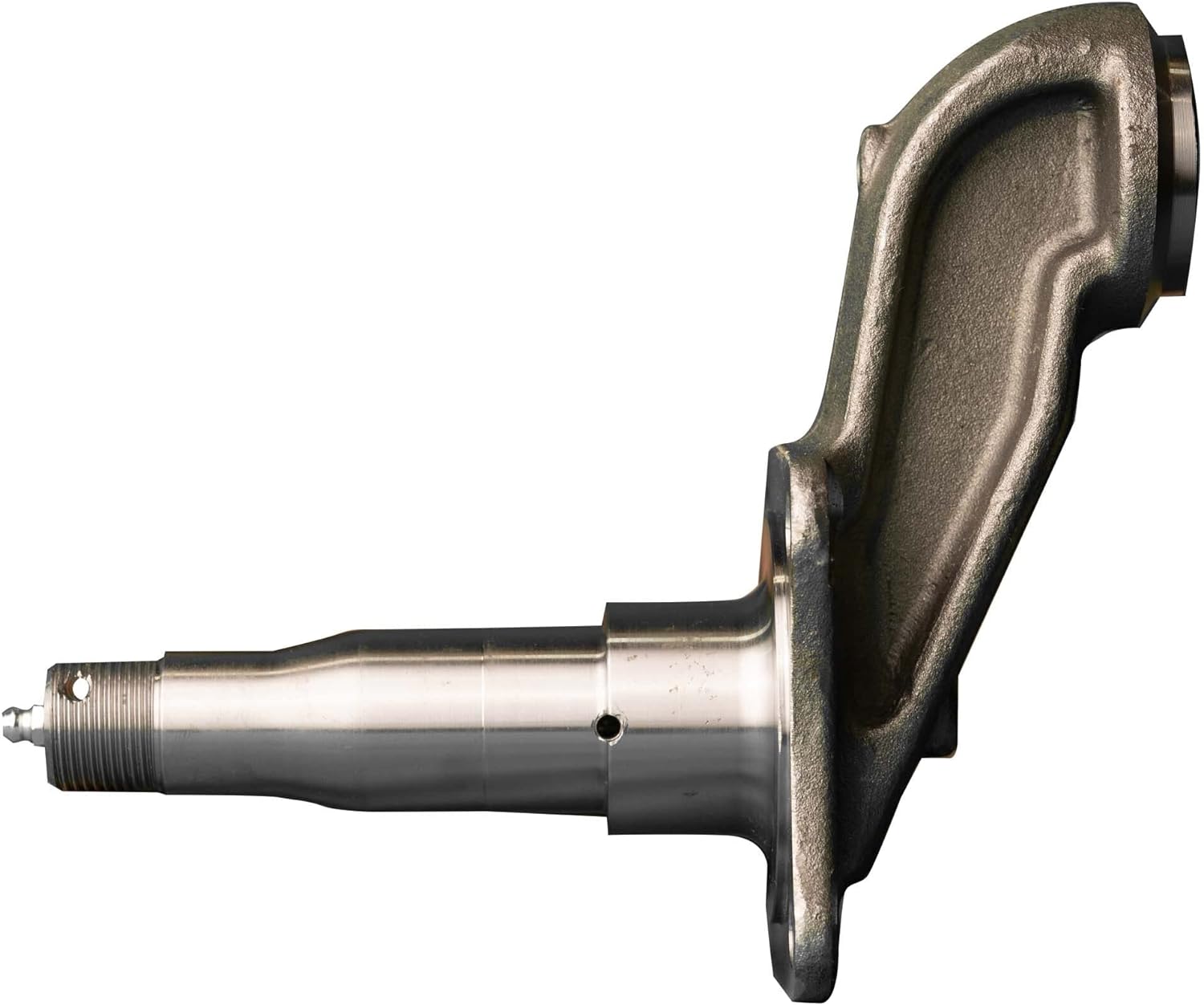
Can a malfunctioning axle spindle lead to brake-related issues, and if so, how?
Yes, a malfunctioning axle spindle can indeed lead to brake-related issues in a vehicle. Here is a detailed explanation of how a faulty axle spindle can affect the brake system:
The axle spindle plays a crucial role in the operation of the brake system, particularly in vehicles with disc brakes. It is responsible for supporting the wheel hub and providing a mounting point for various brake components, such as the brake rotor, caliper, and brake pads. When the axle spindle malfunctions, it can have several adverse effects on the brake system, including the following:
- Uneven Brake Pad Wear: A malfunctioning axle spindle can cause uneven distribution of braking force on the brake rotor. This uneven force can lead to uneven wear of the brake pads. Some pads may wear out faster than others, resulting in uneven braking performance and reduced effectiveness.
- Brake Caliper Misalignment: If the axle spindle becomes bent or damaged, it can cause misalignment of the brake caliper. The caliper may not sit properly over the brake rotor, resulting in uneven braking force or even constant contact between the brake pads and rotor. This can lead to excessive heat, premature wear of brake components, and reduced braking efficiency.
- Brake Vibration and Noise: A malfunctioning axle spindle can cause vibrations and noise during braking. For example, if the spindle is bent or warped, it can create an uneven surface for the brake rotor. As a result, when the brake pads come into contact with the rotor, it can cause vibrations, squealing, or grinding noises. These symptoms indicate a compromised braking performance and the need for axle spindle inspection and repair.
- Wheel Bearing Damage: The axle spindle is closely connected to the wheel bearing assembly. If the spindle is damaged or improperly aligned, it can put excessive stress on the wheel bearing, leading to its premature wear or failure. A worn or damaged wheel bearing can introduce additional friction, affect wheel rotation, and potentially cause overheating of the brake components.
- Brake Fluid Leakage: In certain cases, a malfunctioning axle spindle can result in damage to the brake lines or connections. For example, if the spindle is severely damaged due to an accident or collision, it can cause brake fluid leakage. Brake fluid leakage compromises the hydraulic pressure in the brake system, leading to reduced braking performance or a complete brake failure.
It’s important to note that the specific brake-related issues resulting from a malfunctioning axle spindle can vary depending on the extent and nature of the spindle’s malfunction. Regular inspection and maintenance of the axle spindle, along with the brake system, are essential to identify any potential issues early and prevent further damage.
If you experience any brake-related symptoms or suspect a malfunctioning axle spindle, it is crucial to have the vehicle inspected by a qualified mechanic or technician. They can assess the condition of the axle spindle, perform necessary repairs or replacements, and ensure the proper functioning of the brake system for safe driving.
In summary, a malfunctioning axle spindle can lead to various brake-related issues, including uneven brake pad wear, brake caliper misalignment, brake vibration and noise, wheel bearing damage, and brake fluid leakage. Regular inspection and maintenance of the axle spindle and brake system are essential to prevent these issues and maintain optimal braking performance.
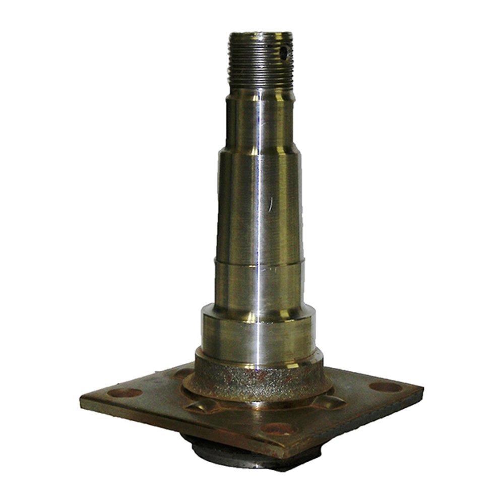
Are there recalls or common issues associated with specific axle spindle models?
Recalls and common issues can occur with specific axle spindle models. Here is a detailed explanation:
Axle spindles are critical components of a vehicle’s suspension system, responsible for supporting the weight of the vehicle and allowing the wheels to rotate. While axle spindle issues are not as common as some other automotive problems, they can still arise in certain situations or with specific models. It’s important to note that recalls and common issues can vary depending on the vehicle make, model, and year. Therefore, it’s essential to consult the manufacturer’s documentation or contact authorized dealerships to obtain the most accurate and up-to-date information regarding recalls or known problems associated with specific axle spindle models.
Recalls are typically issued by vehicle manufacturers or regulatory agencies when a safety-related defect or non-compliance with safety standards is identified in a specific component or vehicle model. When it comes to axle spindles, recalls may be issued if there is evidence of a manufacturing defect, design flaw, or other issues that could compromise the performance, durability, or safety of the axle spindle. Recalls are intended to address these concerns and ensure that affected vehicles are repaired or modified to rectify the problem.
Common issues associated with specific axle spindle models can also arise due to various factors. These issues may be reported by vehicle owners, observed by mechanics or technicians, or identified through data analysis. Common issues can include premature wear, excessive play, bearing failures, or other forms of damage or deterioration that affect the functionality or reliability of the axle spindle.
To determine if there are any recalls or common issues associated with a specific axle spindle model, follow these steps:
- Refer to Manufacturer’s Documentation: Check the manufacturer’s documentation, such as owner’s manuals, maintenance guides, or technical service bulletins. These resources may provide information about known issues, recalls, or recommended maintenance procedures for the axle spindle.
- Contact Authorized Dealerships: Reach out to authorized dealerships or service centers for the vehicle make and model. They often have access to the latest information regarding recalls or common axle spindle issues. Provide them with the specific details of your vehicle, including the make, model, year, and vehicle identification number (VIN) if requested.
- Check Government Recall Databases: Government agencies responsible for vehicle safety, such as the National Highway Traffic Safety Administration (NHTSA) in the United States, maintain databases of recalls. Visit their websites and search for any recalls associated with the specific vehicle make, model, and year.
- Online Forums and Communities: Explore online automotive forums and communities dedicated to the specific vehicle make or model. These platforms often provide valuable insights from owners who may have encountered axle spindle issues or recalls. However, exercise caution and verify the information obtained from such sources, as it may not always be accurate or up to date.
By following these steps, you can gather information about recalls or common issues associated with specific axle spindle models. If a recall or known issue is identified, it’s important to take appropriate action by contacting authorized repair facilities or dealerships to address the problem promptly.
It’s worth noting that not all axle spindle models may have recalls or common issues. Vehicle manufacturers strive to design and produce reliable components, and any potential problems are typically addressed through quality control measures and continuous improvement processes. However, occasional issues can still arise, particularly in specific production runs or under certain operating conditions.
In summary, recalls and common issues can occur with specific axle spindle models. Recalls are typically issued by manufacturers or regulatory agencies to address safety-related defects or non-compliance with safety standards. Common issues can include premature wear, excessive play, bearing failures, or other forms of damage or deterioration. To obtain accurate information about recalls or known issues, refer to the manufacturer’s documentation, contact authorized dealerships, check government recall databases, and explore online forums and communities dedicated to the specific vehicle make or model.
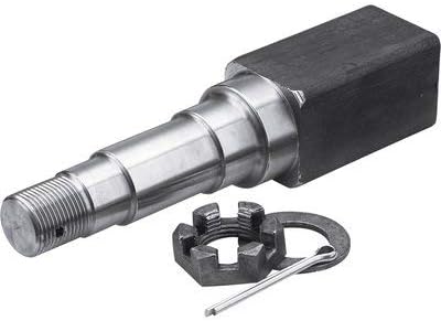
How does a damaged or bent axle spindle impact the performance of a vehicle?
A damaged or bent axle spindle can significantly impact the performance and safety of a vehicle. Here’s a detailed explanation:
When the axle spindle is damaged or bent, it can cause various issues that affect the overall performance and handling of the vehicle. Here are some ways a damaged or bent axle spindle can impact a vehicle:
- Wheel Misalignment: A damaged or bent axle spindle can result in wheel misalignment. This misalignment can cause uneven tire wear, reduced traction, and compromised handling. The vehicle may pull to one side, and the steering may feel unstable or imprecise. Wheel misalignment can also lead to increased rolling resistance, negatively impacting fuel efficiency.
- Vibration and Shaking: A bent axle spindle can cause vibrations and shaking in the vehicle, particularly at higher speeds. The imbalance created by the bent spindle can result in uneven tire rotation and wheel wobbling, leading to an uncomfortable and potentially unsafe driving experience.
- Braking Issues: A damaged axle spindle can affect the performance of the braking system. Uneven wheel rotation caused by a bent spindle can result in inconsistent braking force distribution. This can lead to longer braking distances, reduced braking efficiency, and potentially compromised safety in emergency braking situations.
- Suspension Component Stress: A damaged or bent axle spindle can place excessive stress on other suspension components, such as wheel bearings, control arms, or steering linkage. The misalignment and increased forces can accelerate wear and tear on these components, leading to premature failure and costly repairs.
- Handling and Stability: A compromised axle spindle can negatively impact the vehicle’s handling and stability. It can cause unpredictable steering response, reduced cornering ability, and decreased overall stability during maneuvers. This can increase the risk of loss of control and accidents, especially in emergency or evasive driving situations.
It’s important to address a damaged or bent axle spindle promptly. Continuing to drive with a damaged spindle can exacerbate the issues mentioned above and potentially cause further damage to other components of the suspension system. If you suspect a problem with the axle spindle, it’s recommended to have the vehicle inspected by a qualified mechanic or technician who can accurately diagnose the issue and perform the necessary repairs or replacement.
In summary, a damaged or bent axle spindle can have a significant impact on the performance and safety of a vehicle. It can cause wheel misalignment, vibrations, braking issues, stress on suspension components, and compromised handling and stability. Prompt attention and repair are crucial to ensure the vehicle’s optimal performance and to maintain safety on the road.


editor by CX 2024-02-17
China Hot selling Professional Micro Knurling Stainless Steel High Tolerance Electric Motor Fan Shaft by CNC Turning near me factory
Product Description
Product Description
| Business type | Factory/manufacturer |
|
Service |
CNC machining |
| Turning and milling | |
| CNC turning | |
| OEM parts | |
|
Material |
(1) Aluminum:AL 6061-T6,6063,7075-T |
| (2)Stainless steel:303,304,316L,17-4(SUS630) | |
| (3)Steel:4140,Q235,Q345B,20#,45# | |
| (4)Titanium:TA1,TA2/GR2,TA4/GR5,TC4,TC18 | |
| (5)Brass:C36000(HPb62),C37700(HPb59),C26800(H68) | |
| (6)Copper, bronze, magnesium alloy, Delan, POM, acrylic, PC, etc. | |
| Service | OEM/ODM avaliable |
|
Finish |
Sandblasting, anodizing, Blackenning, zinc/Nickl plating, Poland |
| Powder coating, passivation PVD plating titanium, electrogalvanization | |
| Chrome plating, electrophoresis, QPQ | |
| Electrochemical polishing, chrome plating, knurling, laser etching Logo | |
| Major equipment | CNC machining center (milling machine), CNC lathe, grinding machine |
| Cylindrical grinding machine, drilling machine, laser cutting machine | |
| Graphic format | STEP, STP, GIS, CAD, PDF, DWG, DXF and other samples |
| Tolerance | +/-0.003mm |
| Surface roughness | Ra0.1~3.2 |
| Inspection | Complete testing laboratory with micrometer, optical comparator, caliper vernier, CMM |
| Depth caliper vernier, universal protractor, clock gauge, internal Celsius gauge |
Detailed Photos
Product Parameters
| MATERIAL AVAILABLE | |||||
| Aluminum | Stainless Steel | Brass | Copper | Plastic | Iron |
| AL2571 | SS201 | C22000 | C15710 | POM | Q235 |
| ALA380 | SS301 | C24000 | C11000 | PEEK | Q345B |
| AL5052 | SS303 | C26000 | C12000 | PVC | 1214 / 1215 |
| AL6061 | SS304 | C28000 | C12200 | ABS | 45# |
| AL6063 | SS316 | C35600 | etc. | Nylon | 20# |
| AL6082 | SS416 | C36000 | PP | 4140 / 4130 | |
| AL7075 | etc. | C37000 | Delrin | 12L14 | |
| etc. | etc. | etc. | etc. | ||
| SURFACE TREATMENT | |||||
| Aluminum Parts | Stainless Steel Parts | Steel Parts | Brass Parts | ||
| Clear Anodized | Polishing | Zinc Plating | Nickel Plating | ||
| Color Anodized | Passivating | Oxide black | chrome plating | ||
| Sandblast Anodized | Sandblasting | Nickel Plating | Electrophoresis black | ||
| Chemical Film | Laser engraving | Powder Coated | Powder coated | ||
| Brushing | Electrophoresis black | Heat treatment | Gold plating | ||
| Polishing | Oxide black | Chrome Plating | etc. | ||
| Chroming | etc | etc | |||
| etc | |||||
| TOLERANCE | |||||
| The smallest tolerance can reach +/-0.001mm or as per drawing request. | |||||
| DRAWING FORMAT | |||||
| PFD | Step | Igs | CAD | Solid | etc |
Packaging & Shipping
Company Profile
HangZhou Shinemotor Co.,Ltd located in HangZhou City, ZheJiang Province of China.
Mainly specializes in developing, manufacturing and selling all kinds of customized metal and plastic parts.
Our factory pass SGS, ISO9001/ ISO9001/ ISO14001 verification, parts can be widely used in the fields of automobile,
medical instruments, electronic communications, industrial and consumer applications and so on.
We have introduced a series of advanced and high performance production equipment imported from Japan and ZheJiang :
High precision cnc lathes, 5/6 axis cnc machining centers, plane grinding & centerless grinding machines,
stamping machines, wire cut machines, EDM and many other high-precision CNC equipment.
Our inspection equipment includes: projector, 2D, 2.5D, CMM, hardness testing machine, tool microscope, etc.
We dedicated to developing and producing kinds of brass, aluminum, steel, stainless steel
And plastic machining parts, stamping parts, and also CZPT design and manufacturing.
We firmly hold the concept of ” customer is the first, honesty is the basic, accrete win-win “.
Dedicated to providing you with high-quality products and excellent service!
We sincerely look forward to creating a better future by mutually beneficial cooperation with you.
FAQ
1. Are you a factory or a trading company?
A: We are a factory which has been specialized in cnc machining & automatic manufacturing for more than 10 years.
2. Where is your factory and how can I visit it?
A: Our factory is located in HangZhou city and you can get more detailed information by browsing our website.
3. How long can I get some samples for checking and what about the price?
A: Normally samples will be done within 1-2 days (automatic machining parts) or 3-5 day (cnc machining parts).
The sample cost depends on all information (size, material, finish, etc.).
We will return the sample cost if your order quantity is good.
4. How is the warranty of the products quality control?
A: We hold the tightend quality controlling from very begining to the end and aim at 100% error free.
5.How to get an accurate quotation?
♦ Drawings, photos, detailed sizes or samples of products.
♦ Material of products.
♦ Ordinary purchasing quantity.
♦ Quotation within 1~6 hours
How to Calculate Stiffness, Centering Force, Wear and Fatigue Failure of Spline Couplings
There are various types of spline couplings. These couplings have several important properties. These properties are: Stiffness, Involute splines, Misalignment, Wear and fatigue failure. To understand how these characteristics relate to spline couplings, read this article. It will give you the necessary knowledge to determine which type of coupling best suits your needs. Keeping in mind that spline couplings are usually spherical in shape, they are made of steel.
Involute splines
An effective side interference condition minimizes gear misalignment. When 2 splines are coupled with no spline misalignment, the maximum tensile root stress shifts to the left by 5 mm. A linear lead variation, which results from multiple connections along the length of the spline contact, increases the effective clearance or interference by a given percentage. This type of misalignment is undesirable for coupling high-speed equipment.
Involute splines are often used in gearboxes. These splines transmit high torque, and are better able to distribute load among multiple teeth throughout the coupling circumference. The involute profile and lead errors are related to the spacing between spline teeth and keyways. For coupling applications, industry practices use splines with 25 to 50-percent of spline teeth engaged. This load distribution is more uniform than that of conventional single-key couplings.
To determine the optimal tooth engagement for an involved spline coupling, Xiangzhen Xue and colleagues used a computer model to simulate the stress applied to the splines. The results from this study showed that a “permissible” Ruiz parameter should be used in coupling. By predicting the amount of wear and tear on a crowned spline, the researchers could accurately predict how much damage the components will sustain during the coupling process.
There are several ways to determine the optimal pressure angle for an involute spline. Involute splines are commonly measured using a pressure angle of 30 degrees. Similar to gears, involute splines are typically tested through a measurement over pins. This involves inserting specific-sized wires between gear teeth and measuring the distance between them. This method can tell whether the gear has a proper tooth profile.
The spline system shown in Figure 1 illustrates a vibration model. This simulation allows the user to understand how involute splines are used in coupling. The vibration model shows 4 concentrated mass blocks that represent the prime mover, the internal spline, and the load. It is important to note that the meshing deformation function represents the forces acting on these 3 components.
Stiffness of coupling
The calculation of stiffness of a spline coupling involves the measurement of its tooth engagement. In the following, we analyze the stiffness of a spline coupling with various types of teeth using 2 different methods. Direct inversion and blockwise inversion both reduce CPU time for stiffness calculation. However, they require evaluation submatrices. Here, we discuss the differences between these 2 methods.
The analytical model for spline couplings is derived in the second section. In the third section, the calculation process is explained in detail. We then validate this model against the FE method. Finally, we discuss the influence of stiffness nonlinearity on the rotor dynamics. Finally, we discuss the advantages and disadvantages of each method. We present a simple yet effective method for estimating the lateral stiffness of spline couplings.
The numerical calculation of the spline coupling is based on the semi-analytical spline load distribution model. This method involves refined contact grids and updating the compliance matrix at each iteration. Hence, it consumes significant computational time. Further, it is difficult to apply this method to the dynamic analysis of a rotor. This method has its own limitations and should be used only when the spline coupling is fully investigated.
The meshing force is the force generated by a misaligned spline coupling. It is related to the spline thickness and the transmitting torque of the rotor. The meshing force is also related to the dynamic vibration displacement. The result obtained from the meshing force analysis is given in Figures 7, 8, and 9.
The analysis presented in this paper aims to investigate the stiffness of spline couplings with a misaligned spline. Although the results of previous studies were accurate, some issues remained. For example, the misalignment of the spline may cause contact damages. The aim of this article is to investigate the problems associated with misaligned spline couplings and propose an analytical approach for estimating the contact pressure in a spline connection. We also compare our results to those obtained by pure numerical approaches.
Misalignment
To determine the centering force, the effective pressure angle must be known. Using the effective pressure angle, the centering force is calculated based on the maximum axial and radial loads and updated Dudley misalignment factors. The centering force is the maximum axial force that can be transmitted by friction. Several published misalignment factors are also included in the calculation. A new method is presented in this paper that considers the cam effect in the normal force.
In this new method, the stiffness along the spline joint can be integrated to obtain a global stiffness that is applicable to torsional vibration analysis. The stiffness of bearings can also be calculated at given levels of misalignment, allowing for accurate estimation of bearing dimensions. It is advisable to check the stiffness of bearings at all times to ensure that they are properly sized and aligned.
A misalignment in a spline coupling can result in wear or even failure. This is caused by an incorrectly aligned pitch profile. This problem is often overlooked, as the teeth are in contact throughout the involute profile. This causes the load to not be evenly distributed along the contact line. Consequently, it is important to consider the effect of misalignment on the contact force on the teeth of the spline coupling.
The centre of the male spline in Figure 2 is superposed on the female spline. The alignment meshing distances are also identical. Hence, the meshing force curves will change according to the dynamic vibration displacement. It is necessary to know the parameters of a spline coupling before implementing it. In this paper, the model for misalignment is presented for spline couplings and the related parameters.
Using a self-made spline coupling test rig, the effects of misalignment on a spline coupling are studied. In contrast to the typical spline coupling, misalignment in a spline coupling causes fretting wear at a specific position on the tooth surface. This is a leading cause of failure in these types of couplings.
Wear and fatigue failure
The failure of a spline coupling due to wear and fatigue is determined by the first occurrence of tooth wear and shaft misalignment. Standard design methods do not account for wear damage and assess the fatigue life with big approximations. Experimental investigations have been conducted to assess wear and fatigue damage in spline couplings. The tests were conducted on a dedicated test rig and special device connected to a standard fatigue machine. The working parameters such as torque, misalignment angle, and axial distance have been varied in order to measure fatigue damage. Over dimensioning has also been assessed.
During fatigue and wear, mechanical sliding takes place between the external and internal splines and results in catastrophic failure. The lack of literature on the wear and fatigue of spline couplings in aero-engines may be due to the lack of data on the coupling’s application. Wear and fatigue failure in splines depends on a number of factors, including the material pair, geometry, and lubrication conditions.
The analysis of spline couplings shows that over-dimensioning is common and leads to different damages in the system. Some of the major damages are wear, fretting, corrosion, and teeth fatigue. Noise problems have also been observed in industrial settings. However, it is difficult to evaluate the contact behavior of spline couplings, and numerical simulations are often hampered by the use of specific codes and the boundary element method.
The failure of a spline gear coupling was caused by fatigue, and the fracture initiated at the bottom corner radius of the keyway. The keyway and splines had been overloaded beyond their yield strength, and significant yielding was observed in the spline gear teeth. A fracture ring of non-standard alloy steel exhibited a sharp corner radius, which was a significant stress raiser.
Several components were studied to determine their life span. These components include the spline shaft, the sealing bolt, and the graphite ring. Each of these components has its own set of design parameters. However, there are similarities in the distributions of these components. Wear and fatigue failure of spline couplings can be attributed to a combination of the 3 factors. A failure mode is often defined as a non-linear distribution of stresses and strains.


China factory Gold Supplier Grinding and Hard Chrome Plated Linear 20mm Motor Shaft with high quality
Product Description
1. Description
|
Product name |
304 stainless steel shaft |
|
Material |
Stainless Steel,Aluminum,Brass, Bronze,Carbon steel and ect. environmental protection material. |
|
Size |
Customized according to your drawing. |
|
Services |
OEM, design, customized |
|
Tolerance |
+/-0.01mm to +/-0.005mm |
|
Surface treatment |
Passivation *Polishing *Anodizing *Sand blasting *Electroplating(color, blue, white, black zinc, Ni, Cr, tin, copper, silver) *Black oxide coating *Heat-disposing *Hot-dip galvanizing *Rust preventive oil |
|
MOQ |
1 piece Copper bushing |
|
Samples |
We can make sample within 7days free of charge |
|
Certificate |
ISO9001:2015 cnc machining turning parts shaft |
|
Payment Terms |
Bank Transfer;Western Union; Paypal ; Payoneer, Alibaba Trade Assurance30% deposit & balance before shipping. |
|
Delivery time |
Within 15-20 workdays after deposit or payment received |
|
Shipping Port |
HangZhou 304 stainless steel shaft |
2. Main Motor Shafts
3. Work Flow
4. Application
5. About US
What Are the Advantages of a Splined Shaft?
If you are looking for the right splined shaft for your machine, you should know a few important things. First, what type of material should be used? Stainless steel is usually the most appropriate choice, because of its ability to offer low noise and fatigue failure. Secondly, it can be machined using a slotting or shaping machine. Lastly, it will ensure smooth motion. So, what are the advantages of a splined shaft?
Stainless steel is the best material for splined shafts
When choosing a splined shaft, you should consider its hardness, quality, and finish. Stainless steel has superior corrosion and wear resistance. Carbon steel is another good material for splined shafts. Carbon steel has a shallow carbon content (about 1.7%), which makes it more malleable and helps ensure smooth motion. But if you’re not willing to spend the money on stainless steel, consider other options.
There are 2 main types of splines: parallel splines and crowned splines. Involute splines have parallel grooves and allow linear and rotary motion. Helical splines have involute teeth and are oriented at an angle. This type allows for many teeth on the shaft and minimizes the stress concentration in the stationary joint.
Large evenly spaced splines are widely used in hydraulic systems, drivetrains, and machine tools. They are typically made from carbon steel (CR10) and stainless steel (AISI 304). This material is durable and meets the requirements of ISO 14-B, formerly DIN 5463-B. Splined shafts are typically made of stainless steel or C45 steel, though there are many other materials available.
Stainless steel is the best material for a splined shaft. This metal is also incredibly affordable. In most cases, stainless steel is the best choice for these shafts because it offers the best corrosion resistance. There are many different types of splined shafts, and each 1 is suited for a particular application. There are also many different types of stainless steel, so choose stainless steel if you want the best quality.
For those looking for high-quality splined shafts, CZPT Spline Shafts offer many benefits. They can reduce costs, improve positional accuracy, and reduce friction. With the CZPT TFE coating, splined shafts can reduce energy and heat buildup, and extend the life of your products. And, they’re easy to install – all you need to do is install them.
They provide low noise, low wear and fatigue failure
The splines in a splined shaft are composed of 2 main parts: the spline root fillet and the spline relief. The spline root fillet is the most critical part, because fatigue failure starts there and propagates to the relief. The spline relief is more susceptible to fatigue failure because of its involute tooth shape, which offers a lower stress to the shaft and has a smaller area of contact.
The fatigue life of splined shafts is determined by measuring the S-N curve. This is also known as the Wohler curve, and it is the relationship between stress amplitude and number of cycles. It depends on the material, geometry and way of loading. It can be obtained from a physical test on a uniform material specimen under a constant amplitude load. Approximations for low-alloy steel parts can be made using a lower-alloy steel material.
Splined shafts provide low noise, minimal wear and fatigue failure. However, some mechanical transmission elements need to be removed from the shaft during assembly and manufacturing processes. The shafts must still be capable of relative axial movement for functional purposes. As such, good spline joints are essential to high-quality torque transmission, minimal backlash, and low noise. The major failure modes of spline shafts include fretting corrosion, tooth breakage, and fatigue failure.
The outer disc carrier spline is susceptible to tensile stress and fatigue failure. High customer demands for low noise and low wear and fatigue failure makes splined shafts an excellent choice. A fractured spline gear coupling was received for analysis. It was installed near the top of a filter shaft and inserted into the gearbox motor. The service history was unknown. The fractured spline gear coupling had longitudinally cracked and arrested at the termination of the spline gear teeth. The spline gear teeth also exhibited wear and deformation.
A new spline coupling method detects fault propagation in hollow cylindrical splined shafts. A spline coupling is fabricated using an AE method with the spline section unrolled into a metal plate of the same thickness as the cylinder wall. In addition, the spline coupling is misaligned, which puts significant concentration on the spline teeth. This further accelerates the rate of fretting fatigue and wear.
A spline joint should be lubricated after 25 hours of operation. Frequent lubrication can increase maintenance costs and cause downtime. Moreover, the lubricant may retain abrasive particles at the interfaces. In some cases, lubricants can even cause misalignment, leading to premature failure. So, the lubrication of a spline coupling is vital in ensuring proper functioning of the shaft.
The design of a spline coupling can be optimized to enhance its wear resistance and reliability. Surface treatments, loads, and rotation affect the friction properties of a spline coupling. In addition, a finite element method was developed to predict wear of a floating spline coupling. This method is feasible and provides a reliable basis for predicting the wear and fatigue life of a spline coupling.
They can be machined using a slotting or shaping machine
Machines can be used to shape splined shafts in a variety of industries. They are useful in many applications, including gearboxes, braking systems, and axles. A slotted shaft can be manipulated in several ways, including hobbling, broaching, and slotting. In addition to shaping, splines are also useful in reducing bar diameter.
When using a slotting or shaping machine, the workpiece is held against a pedestal that has a uniform thickness. The machine is equipped with a stand column and limiting column (Figure 1), each positioned perpendicular to the upper surface of the pedestal. The limiting column axis is located on the same line as the stand column. During the slotting or shaping process, the tool is fed in and out until the desired space is achieved.
One process involves cutting splines into a shaft. Straddle milling, spline shaping, and spline cutting are 2 common processes used to create splined shafts. Straddle milling involves a fixed indexing fixture that holds the shaft steady, while rotating milling cutters cut the groove in the length of the shaft. Several passes are required to ensure uniformity throughout the spline.
Splines are a type of gear. The ridges or teeth on the drive shaft mesh with grooves in the mating piece. A splined shaft allows the transmission of torque to a mate piece while maximizing the power transfer. Splines are used in heavy vehicles, construction, agriculture, and massive earthmoving machinery. Splines are used in virtually every type of rotary motion, from axles to transmission systems. They also offer better fatigue life and reliability.
Slotting or shaping machines can also be used to shape splined shafts. Slotting machines are often used to machine splined shafts, because it is easier to make them with these machines. Using a slotting or shaping machine can result in splined shafts of different sizes. It is important to follow a set of spline standards to ensure your parts are manufactured to the highest standards.
A milling machine is another option for producing splined shafts. A spline shaft can be set up between 2 centers in an indexing fixture. Two side milling cutters are mounted on an arbor and a spacer and shims are inserted between them. The arbor and cutters are then mounted to a milling machine spindle. To make sure the cutters center themselves over the splined shaft, an adjustment must be made to the spindle of the machine.
The machining process is very different for internal and external splines. External splines can be broached, shaped, milled, or hobbed, while internal splines cannot. These machines use hard alloy, but they are not as good for internal splines. A machine with a slotting mechanism is necessary for these operations.
China Professional Motor Shaft Processing Machine Shaft Manufacturing Machine near me manufacturer
Product Description
With high accuracy, high-speed stability, this shaft processing machine is suitable for high accuracy and mass production shaft processing requirement. It can be connected with a automatic feeding machine to achieve continuous process, greatly improving working efficiency.
This machine adopts cast iron framework with a rigidity design The inHangZhou of C axle is of high accuracy. There are 2 types of CZPT sleeve, fixed or flexible one. Customer could choose as per their production requirement. The main spindle and sub-spindle work together.
Techanical dat
|
Control system |
SYNTEC 200TA |
|
|
Max processing OD |
Φ20mm |
|
|
Max travel of main spindle station |
Fixed CZPT sleeve |
210mm |
|
Flexible CZPT sleeve |
80mm |
|
|
Cutter |
Cutter number |
9pcs(5pcs) (12mmx95~135mm) |
|
Front cutter |
Front cutter no. |
4pcs |
|
Max drilling diameter |
Φ8mm |
|
|
Threading capacity |
M8xP1.25 |
|
|
Sub-spindle |
Max drilling diameter |
/ |
|
Threading capacity |
/ |
|
|
Power tool |
Cutter number |
4pcs |
|
Max drilling diameter |
Φ7mm |
|
|
Threading capacity |
M6xP1.0 |
|
|
Main spindle inHangZhou |
C axle |
|
|
Main spindle revolution |
6000rpm |
|
|
Main spindle motor power |
2.9kw |
|
|
Sub-spindle revolution |
/ |
|
|
Sub-spindle motor power |
/ |
|
|
Rapid traverse speed |
32m/min(X:24m/min) |
|
|
Power head revolution |
6000rpm |
|
|
Power head motor power |
0.75kw |
|
|
Dimension |
1660x1050x1740mm |
|
|
Weight |
1800kg |
|
Working station
With good service, unique philosophy, professional team and reliable quality, we win the worldwide customers’ confidence gradually. We directly and indirectly supply our products to more than 50 countries .
| Customerized service | 1. Customized product design and manufacturing |
| 2. Customized trHangZhou | |
| 3.Technical suggestions | |
| After-sales service | 1. Warranty Period: 12 month usually |
| 2. Overseas service center available | |
|
3. Engineers available to service overseas |
Established in 2007, CZPT is a company devoted in the field of electric motors manufacturing, providing one-stop service for its customers.
NIDE has 3 main business divisions.
The first division is to provide different kinds of motor manufacturing machines, it is our Main business, including stand along machine, fully-auto complete line for armature and stator production, and the motor assembly line.
The second division is to supply the full range of motor components such as commutator, ball bearing, carbon brush, insulation paper, shaft, magnet, fan, motor cover, etc.
The third division is to provide technical support and consulting, project support and turn-key service for some motor manufacturing.
The Different Types of Splines in a Splined Shaft
A splined shaft is a machine component with internal and external splines. The splines are formed in 4 different ways: Involute, Parallel, Serrated, and Ball. You can learn more about each type of spline in this article. When choosing a splined shaft, be sure to choose the right 1 for your application. Read on to learn about the different types of splines and how they affect the shaft’s performance.
Involute splines
Involute splines in a splined shaft are used to secure and extend mechanical assemblies. They are smooth, inwardly curving grooves that resist separation during operation. A shaft with involute splines is often longer than the shaft itself. This feature allows for more axial movement. This is beneficial for many applications, especially in a gearbox.
The involute spline is a shaped spline, similar to a parallel spline. It is angled and consists of teeth that create a spiral pattern that enables linear and rotatory motion. It is distinguished from other splines by the serrations on its flanks. It also has a flat top. It is a good option for couplers and other applications where angular movement is necessary.
Involute splines are also called involute teeth because of their shape. They are flat on the top and curved on the sides. These teeth can be either internal or external. As a result, involute splines provide greater surface contact, which helps reduce stress and fatigue. Regardless of the shape, involute splines are generally easy to machine and fit.
Involute splines are a type of splines that are used in splined shafts. These splines have different names, depending on their diameters. An example set of designations is for a 32-tooth male spline, a 2,500-tooth module, and a 30 degree pressure angle. An example of a female spline, a fillet root spline, is used to describe the diameter of the splined shaft.
The effective tooth thickness of splines is dependent on the number of keyways and the type of spline. Involute splines in splined shafts should be designed to engage 25 to 50 percent of the spline teeth during the coupling. Involute splines should be able to withstand the load without cracking.
Parallel splines
Parallel splines are formed on a splined shaft by putting 1 or more teeth into another. The male spline is positioned at the center of the female spline. The teeth of the male spline are also parallel to the shaft axis, but a common misalignment causes the splines to roll and tilt. This is common in many industrial applications, and there are a number of ways to improve the performance of splines.
Typically, parallel splines are used to reduce friction in a rotating part. The splines on a splined shaft are narrower on the end face than the interior, which makes them more prone to wear. This type of spline is used in a variety of industries, such as machinery, and it also allows for greater efficiency when transmitting torque.
Involute splines on a splined shaft are the most common. They have equally spaced teeth, and are therefore less likely to crack due to fatigue. They also tend to be easy to cut and fit. However, they are not the best type of spline. It is important to understand the difference between parallel and involute splines before deciding on which spline to use.
The difference between splined and involute splines is the size of the grooves. Involute splines are generally larger than parallel splines. These types of splines provide more torque to the gear teeth and reduce stress during operation. They are also more durable and have a longer life span. And because they are used on farm machinery, they are essential in this type of application.
Serrated splines
A Serrated Splined Shaft has several advantages. This type of shaft is highly adjustable. Its large number of teeth allows large torques, and its shorter tooth width allows for greater adjustment. These features make this type of shaft an ideal choice for applications where accuracy is critical. Listed below are some of the benefits of this type of shaft. These benefits are just a few of the advantages. Learn more about this type of shaft.
The process of hobbing is inexpensive and highly accurate. It is useful for external spline shafts, but is not suitable for internal splines. This type of process forms synchronized shapes on the shaft, reducing the manufacturing cycle and stabilizing the relative phase between spline and thread. It uses a grinding wheel to shape the shaft. CZPT Manufacturing has a large inventory of Serrated Splined Shafts.
The teeth of a Serrated Splined Shaft are designed to engage with the hub over the entire circumference of the shaft. The teeth of the shaft are spaced uniformly around the spline, creating a multiple-tooth point of contact over the entire length of the shaft. The results of these analyses are usually satisfactory. But there are some limitations. To begin with, the splines of the Serrated Splined Shaft should be chosen carefully. If the application requires large-scale analysis, it may be necessary to modify the design.
The splines of the Serrated Splined Shaft are also used for other purposes. They can be used to transmit torque to another device. They also act as an anti-rotational device and function as a linear guide. Both the design and the type of splines determine the function of the Splined Shaft. In the automobile industry, they are used in vehicles, aerospace, earth-moving machinery, and many other industries.
Ball splines
The invention relates to a ball-spinned shaft. The shaft comprises a plurality of balls that are arranged in a series and are operatively coupled to a load path section. The balls are capable of rolling endlessly along the path. This invention also relates to a ball bearing. Here, a ball bearing is 1 of the many types of gears. The following discussion describes the features of a ball bearing.
A ball-splined shaft assembly comprises a shaft with at least 1 ball-spline groove and a plurality of circumferential step grooves. The shaft is held in a first holding means that extends longitudinally and is rotatably held by a second holding means. Both the shaft and the first holding means are driven relative to 1 another by a first driving means. It is possible to manufacture a ball-splined shaft in a variety of ways.
A ball-splined shaft features a nut with recirculating balls. The ball-splined nut rides in these grooves to provide linear motion while preventing rotation. A splined shaft with a nut that has recirculating balls can also provide rotary motion. A ball splined shaft also has higher load capacities than a ball bushing. For these reasons, ball splines are an excellent choice for many applications.
In this invention, a pair of ball-spinned shafts are housed in a box under a carrier device 40. Each of the 2 shafts extends along a longitudinal line of arm 50. One end of each shaft is supported rotatably by a slide block 56. The slide block also has a support arm 58 that supports the center arm 50 in a cantilever fashion.
Sector no-go gage
A no-go gauge is a tool that checks the splined shaft for oversize. It is an effective way to determine the oversize condition of a splined shaft without removing the shaft. It measures external splines and serrations. The no-go gage is available in sizes ranging from 19mm to 130mm with a 25mm profile length.
The sector no-go gage has 2 groups of diametrally opposed teeth. The space between them is manufactured to a maximum space width and the tooth thickness must be within a predetermined tolerance. This gage would be out of tolerance if the splines were measured with a pin. The dimensions of this splined shaft can be found in the respective ANSI or DIN standards.
The go-no-go gage is useful for final inspection of thread pitch diameter. It is also useful for splined shafts and threaded nuts. The thread of a screw must match the contour of the go-no-go gage head to avoid a no-go condition. There is no substitute for a quality machine. It is an essential tool for any splined shaft and fastener manufacturer.
The NO-GO gage can detect changes in tooth thickness. It can be calibrated under ISO17025 standards and has many advantages over a non-go gage. It also gives a visual reference of the thickness of a splined shaft. When the teeth match, the shaft is considered ready for installation. It is a critical process. In some cases, it is impossible to determine the precise length of the shaft spline.
The 45-degree pressure angle is most commonly used for axles and torque-delivering members. This pressure angle is the most economical in terms of tool life, but the splines will not roll neatly like a 30 degree angle. The 45-degree spline is more likely to fall off larger than the other two. Oftentimes, it will also have a crowned look. The 37.5 degree pressure angle is a compromise between the other 2 pressure angles. It is often used when the splined shaft material is harder than usual.
China OEM AX17 Yanma VIO17 VIO20 Kubot U17 U18 ZAXIS ZX17 Mini Crawler Digger Excavator Swing Motor Parts Drive Shaft wholesaler
Situation: New
Relevant Industries: Machinery Restore Retailers, Development works , Energy & Mining
Showroom Area: None
Online video outgoing-inspection: Presented
Machinery Test Report: Not Available
Advertising Type: Ordinary Product
Warranty: 3 Months
Portion title: Swing Drive Motor Shaft Pinion
Model: AX17 VIO17 VIO18 U17 U18 ZX17
Component Quantity: Shaft Pinion, Swing
Application: Swing Gadget Motor Reduction
Overall performance: Excavator Slewing Swing Push
Following Warranty Support: On the web assist, Spare areas
Nearby Service Location: None
Right after-product sales Service Presented: On the internet help, Free spare elements
Packaging Information: PP BagCartonPlywood CaseMini Crawler Digger Areas VIO20 VIO25 VIO30 VIO35 VIO40 VIO50 Yanma Excavator Swing Push Motor Reduction Shaft Pinion
AX17 Yanma VIO17 VIO20 Kubot U17 U18 ZAXIS ZX17 Mini Crawler Digger Excavator Swing Motor Parts Push ShaftMini excavator swing push shaft
Crawler Digger Parts Mini Excavator Areas IHI18 Swing Motor Drive Shaft
K3V Hydraulic pumpK3V63DT/ K3V63DTP, K3V112DT/ K3V112DTP, K3V140DT/ K3V140DTP K3V180DT/ K3V180DTH, K3V280DT/ K3V280DTHK5V Hydraulic pumpK5V63/ K5V70DTP, K5V112DTP, K5V140DTPMX Hydraulic motorMX50, MX80, MX150, Agricultural machinery elements Agriculture Tube Spline CZPT Tractor Truck Rotary Shaft Adapter Pto Generate Shaft With Clutch Yoke MX173, MX200, MX250, MX300, MX450, MX500, MX530, MX750MB Hydraulic motorMB500, MB550, MB750M2X Hydraulic motorM2X55, M2X63, M2X96, M2X96, 225711-P23 Excellent Wall Wingle authentic high quality front axle generate shaft M2X120, M2X128, M2X146,M2X Hydraulic Swing MotorM2X150, M2X170, M2X210M5X Hydraulic motorM5X130, M5X160, M5X180 DNB Hydraulic travel motorDNB50B, DNB50V, DNB60BHPV Hydraulic pumpMachine model HPV125B Hydraulic PumpUH07-7, UH083, UH143, UH123 HPV125A Hydraulic pumpUH261, China high quality S688zz rowing equipment seat nylon pulley wheels 4×25.4x6mm UH09-7, UH10LC-1/2, DH10 HPVO55 Hydraulic PumpEX100-3/5, EX120-3/5 HPVO102 Hydraulic PumpEX200-5, EX220-5HPVO102 Hydraulic PumpZAXIS200, ZAXSI220, ZAXSI250HPVO91DW Hydraulic PumpEX200-2, EX220-2HPVO91EW Hydraulic PumpEX200-3, EX220-3 HPVO91DS Hydraulic PumpEX100-2, EX100M-2, EX120-3 HPV116C/HPV116D/ HPV116FEX190,EX200,EX220HPV145C Hydraulic PumpEX265-1/2/3/5, Customized Timing Belt Pulley Bushing Steel Pulleys Wheel EX300-1/2/3/5 HPV145D Hydraulic PumpEX350-5, EX330-5, EX370-5HPV145F Hydraulic Pump
Why Checking the Push Shaft is Crucial
If you listen to clicking noises while driving, your driveshaft might want fix. An knowledgeable mechanic can explain to if the sound is coming from one aspect or the two sides. This issue is typically relevant to the torque converter. Go through on to discover why it truly is so important to have your driveshaft inspected by an auto mechanic. Listed here are some signs and symptoms to seem for. Clicking noises can be induced by several diverse factors. You should initial check if the sound is coming from the front or the rear of the automobile.
hollow drive shaft
Hollow driveshafts have many rewards. They are light-weight and decrease the all round excess weight of the vehicle. The largest producer of these elements in the planet is CZPT. They also supply light-weight answers for various purposes, these kinds of as substantial-efficiency axles. CZPT driveshafts are manufactured employing point out-of-the-artwork technological innovation. They supply excellent top quality at competitive rates.
The inner diameter of the hollow shaft lowers the magnitude of the inner forces, thereby decreasing the volume of torque transmitted. Unlike sound shafts, hollow shafts are obtaining much better. The content inside of the hollow shaft is a bit lighter, which even more lowers its bodyweight and total torque. However, this also boosts its drag at higher speeds. This indicates that in many purposes hollow driveshafts are not as productive as strong driveshafts.
A standard hollow drive shaft is made up of a 1st rod 14 and a 2nd rod 14 on the two sides. The 1st rod is connected with the second rod, and the next rod extends in the rotation direction. The two rods are then friction welded to the central spot of the hollow shaft. The frictional warmth created during the relative rotation will help to connect the two parts. Hollow drive shafts can be utilized in internal combustion engines and environmentally-friendly cars.
The main benefit of a hollow driveshaft is excess weight reduction. The splines of the hollow travel shaft can be designed to be more compact than the exterior diameter of the hollow shaft, which can drastically minimize bodyweight. Hollow shafts are also less probably to jam compared to strong shafts. Hollow driveshafts are expected to sooner or later occupy the planet market for automotive driveshafts. Its advantages contain fuel performance and greater overall flexibility in comparison to reliable prop shafts.
Cardan shaft
Cardan shafts are a well-liked option in industrial equipment. They are utilised to transmit electricity from a single machine to an additional and are offered in a assortment of measurements and designs. They are offered in a range of components, which includes metal, copper, and aluminum. If you prepare to set up a single of these shafts, it is crucial to know the various types of Cardan shafts offered. To locate the best selection, look through the catalog.
Telescopic or “Cardan” prop shafts, also acknowledged as U-joints, are excellent for successful torque transfer in between the drive and output program. They are productive, light-weight, and power-successful. They utilize innovative techniques, like finite component modeling (FEM), to guarantee highest performance, weight, and efficiency. Additionally, the Cardan shaft has an adjustable size for effortless repositioning.
One more common selection for driveshafts is the Cardan shaft, also identified as a driveshaft. The purpose of the driveshaft is to transfer torque from the engine to the wheels. They are normally utilised in substantial-functionality auto engines. Some types are produced of brass, iron, or metal and have unique surface area types. Cardan shafts are obtainable in inclined and parallel configurations.
Solitary Cardan shafts are a common replacement for normal Cardan shafts, but if you are looking for dual Cardan shafts for your automobile, you will want to select the 1310 series. This sort is excellent for lifted jeeps and requires a CV-compatible transfer situation. Some even need axle spacers. The dual Cardan shafts are also created for lifts, which means it is a very good option for raising and decreasing jeeps.
common joint
Cardan joints are a great option for travel shafts when operating at a constant pace. Their style makes it possible for a continual angular velocity ratio between the enter and output shafts. Based on the application, the advised pace restrict may possibly vary based on the working angle, transmission electricity, and software. These tips need to be primarily based on strain. The highest permissible speed of the travel shaft is established by figuring out the angular acceleration.
Simply because gimbal joints never require grease, they can final a lengthy time but ultimately are unsuccessful. If they are improperly lubricated or dry, they can trigger steel-to-metal contact. The exact same is accurate for U-joints that do not have oil filling capability. Even though they have a long lifespan, it can be tough to place warning indicators that could reveal impending joint failure. To keep away from this, check the generate shaft regularly.
U-joints ought to not exceed seventy % of their lateral essential velocity. Nonetheless, if this speed is exceeded, the component will knowledge unacceptable vibration, minimizing its helpful daily life. To decide the best U-joint for your software, make sure you get in touch with your universal joint supplier. Typically, lower speeds do not require balancing. In these cases, you should take into account utilizing a larger pitch diameter to lessen axial force.
To reduce the angular velocity and torque of the output shaft, the two joints have to be in section. As a result, the output shaft angular displacement does not totally stick to the enter shaft. Rather, it will guide or lag. Figure 3 illustrates the angular velocity variation and peak displacement direct of the gimbal. The ratios are shown below. The correct torque for this software is 1360 in-Ibs.
Refurbished push shaft
Refurbished driveshafts are a excellent decision for a variety of motives. They are cheaper than brand new alternate options and normally just as trustworthy. Driveshafts are crucial to the purpose of any vehicle, truck, or bus. These elements are produced of hollow metal tubes. While this aids decrease bodyweight and cost, it is susceptible to external influences. If this happens, it may possibly crack or bend. If the shaft suffers this variety of hurt, it can lead to severe harm to the transmission.
A car’s driveshaft is a crucial component that transmits torque from the motor to the wheels. A1 Push Shaft is a worldwide supplier of automotive driveshafts and relevant factors. Their factory has the functionality to refurbish and mend almost any make or product of driveshafts. Refurbished driveshafts are obtainable for each and every make and product of automobile. They can be located on the marketplace for a variety of cars, such as passenger autos, vans, vans, and SUVs.
Strange noises show that your driveshaft demands to be changed. Worn U-joints and bushings can result in excessive vibration. These elements result in wear on other components of the drivetrain. If you recognize any of these indicators, please get your vehicle to the AAMCO Bay Location Middle for a complete inspection. If you suspect hurt to the driveshaft, do not wait one more moment – it can be very dangerous.
The value of changing the travel shaft
The value of changing a driveshaft varies, but on regular, this restore costs amongst $two hundred and $1,five hundred. While this price may differ by motor vehicle, the price of parts and labor is usually equivalent. If you do the fix your self, you must know how a lot the components and labor will cost just before you start function. Some areas can be far more expensive than other individuals, so it truly is a good notion to compare the expense of numerous spots prior to determining exactly where to go.
If you recognize any of these symptoms, you ought to find a restore store immediately. If you are nonetheless not sure if the driveshaft is damaged, do not travel the automobile any distance until finally it is fixed. Symptoms to look for include lack of power, trouble shifting the auto, squeaking, clanking, or vibrating when the car is transferring.
Areas utilised in travel shafts consist of heart help bearings, slip joints, and U-joints. The price tag of the driveshaft differs by automobile and might range by product of the identical 12 months. Also, various varieties of driveshafts call for different mend approaches and are a lot more high-priced. Total, however, a driveshaft substitution fees amongst $300 and $1,three hundred. The approach could consider about an hour, depending on the car model.
Several factors can lead to the need to replace the travel shaft, such as bearing corrosion, damaged seals, or other components. In some instances, the U-joint signifies that the push shaft wants to be changed. Even if the bearings and u-joints are in very good situation, they will at some point crack and call for the substitution of the push shaft. Nevertheless, these elements are not low cost, and if a destroyed driveshaft is a symptom of a greater issue, you must get the time to exchange the shaft.

