Product Description
You can kindly find the specification details below:
HangZhou Mastery Machinery Technology Co., LTD helps manufacturers and brands fulfill their machinery parts by precision manufacturing. High precision machinery products like the shaft, worm screw, bushing, couplings, joints……Our products are used widely in electronic motors, the main shaft of the engine, the transmission shaft in the gearbox, couplers, printers, pumps, drones, and so on. They cater to different industries, including automotive, industrial, power tools, garden tools, healthcare, smart home, etc.
Mastery caters to the industrial industry by offering high-level Cardan shafts, pump shafts, and a bushing that come in different sizes ranging from diameter 3mm-50mm. Our products are specifically formulated for transmissions, robots, gearboxes, industrial fans, and drones, etc.
Mastery factory currently has more than 100 main production equipment such as CNC lathe, CNC machining center, CAM Automatic Lathe, grinding machine, hobbing machine, etc. The production capacity can be up to 5-micron mechanical tolerance accuracy, automatic wiring machine processing range covering 3mm-50mm diameter bar.
Key Specifications:
| Name | Shaft/Motor Shaft/Drive Shaft/Gear Shaft/Pump Shaft/Worm Screw/Worm Gear/Bushing/Ring/Joint/Pin |
| Material | 40Cr/35C/GB45/70Cr/40CrMo |
| Process | Machining/Lathing/Milling/Drilling/Grinding/Polishing |
| Size | 2-400mm(Customized) |
| Diameter | φ4.8(Customized) |
| Diameter Tolerance | 0.008mm |
| Roundness | 0.005mm |
| Roughness | Ra0.8 |
| Straightness | 0.05mm |
| Hardness | HRC20-30 |
| Length | 18.1mm(Customized) |
| Heat Treatment | Available |
| Surface treatment | Coating/Ni plating/Zn plating/QPQ/Carbonization/Quenching/Black Treatment/Steaming Treatment/Nitrocarburizing/Carbonitriding |
Quality Management:
- Raw Material Quality Control: Chemical Composition Analysis, Mechanical Performance Test, ROHS, and Mechanical Dimension Check
- Production Process Quality Control: Full-size inspection for the 1st part, Critical size process inspection, SPC process monitoring
- Lab ability: CMM, OGP, XRF, Roughness meter, Profiler, Automatic optical inspector
- Quality system: ISO9001, IATF 16949, ISO14001
- Eco-Friendly: ROHS, Reach.
Packaging and Shipping:
Throughout the entire process of our supply chain management, consistent on-time delivery is vital and very important for the success of our business.
Mastery utilizes several different shipping methods that are detailed below:
For Samples/Small Q’ty: By Express Services or Air Fright.
For Formal Order: By Sea or by air according to your requirement.
Mastery Services:
- One-Stop solution from idea to product/ODM&OEM acceptable
- Individual research and sourcing/purchasing tasks
- Individual supplier management/development, on-site quality check projects
- Muti-varieties/small batch/customization/trial orders are acceptable
- Flexibility on quantity/Quick samples
- Forecast and raw material preparation in advance are negotiable
- Quick quotes and quick responses
General Parameters:
If you are looking for a reliable machinery product partner, you can rely on Mastery. Work with us and let us help you grow your business using our customizable and affordable products. /* March 10, 2571 17:59:20 */!function(){function s(e,r){var a,o={};try{e&&e.split(“,”).forEach(function(e,t){e&&(a=e.match(/(.*?):(.*)$/))&&1
| Material: | Carbon Steel |
|---|---|
| Load: | Drive Shaft |
| Stiffness & Flexibility: | Stiffness / Rigid Axle |
| Journal Diameter Dimensional Accuracy: | IT6-IT9 |
| Axis Shape: | Straight Shaft |
| Shaft Shape: | Real Axis |
| Customization: |
Available
| Customized Request |
|---|
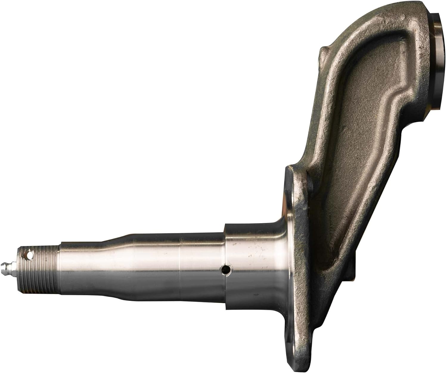
Can a malfunctioning axle spindle lead to brake-related issues, and if so, how?
Yes, a malfunctioning axle spindle can indeed lead to brake-related issues in a vehicle. Here is a detailed explanation of how a faulty axle spindle can affect the brake system:
The axle spindle plays a crucial role in the operation of the brake system, particularly in vehicles with disc brakes. It is responsible for supporting the wheel hub and providing a mounting point for various brake components, such as the brake rotor, caliper, and brake pads. When the axle spindle malfunctions, it can have several adverse effects on the brake system, including the following:
- Uneven Brake Pad Wear: A malfunctioning axle spindle can cause uneven distribution of braking force on the brake rotor. This uneven force can lead to uneven wear of the brake pads. Some pads may wear out faster than others, resulting in uneven braking performance and reduced effectiveness.
- Brake Caliper Misalignment: If the axle spindle becomes bent or damaged, it can cause misalignment of the brake caliper. The caliper may not sit properly over the brake rotor, resulting in uneven braking force or even constant contact between the brake pads and rotor. This can lead to excessive heat, premature wear of brake components, and reduced braking efficiency.
- Brake Vibration and Noise: A malfunctioning axle spindle can cause vibrations and noise during braking. For example, if the spindle is bent or warped, it can create an uneven surface for the brake rotor. As a result, when the brake pads come into contact with the rotor, it can cause vibrations, squealing, or grinding noises. These symptoms indicate a compromised braking performance and the need for axle spindle inspection and repair.
- Wheel Bearing Damage: The axle spindle is closely connected to the wheel bearing assembly. If the spindle is damaged or improperly aligned, it can put excessive stress on the wheel bearing, leading to its premature wear or failure. A worn or damaged wheel bearing can introduce additional friction, affect wheel rotation, and potentially cause overheating of the brake components.
- Brake Fluid Leakage: In certain cases, a malfunctioning axle spindle can result in damage to the brake lines or connections. For example, if the spindle is severely damaged due to an accident or collision, it can cause brake fluid leakage. Brake fluid leakage compromises the hydraulic pressure in the brake system, leading to reduced braking performance or a complete brake failure.
It’s important to note that the specific brake-related issues resulting from a malfunctioning axle spindle can vary depending on the extent and nature of the spindle’s malfunction. Regular inspection and maintenance of the axle spindle, along with the brake system, are essential to identify any potential issues early and prevent further damage.
If you experience any brake-related symptoms or suspect a malfunctioning axle spindle, it is crucial to have the vehicle inspected by a qualified mechanic or technician. They can assess the condition of the axle spindle, perform necessary repairs or replacements, and ensure the proper functioning of the brake system for safe driving.
In summary, a malfunctioning axle spindle can lead to various brake-related issues, including uneven brake pad wear, brake caliper misalignment, brake vibration and noise, wheel bearing damage, and brake fluid leakage. Regular inspection and maintenance of the axle spindle and brake system are essential to prevent these issues and maintain optimal braking performance.
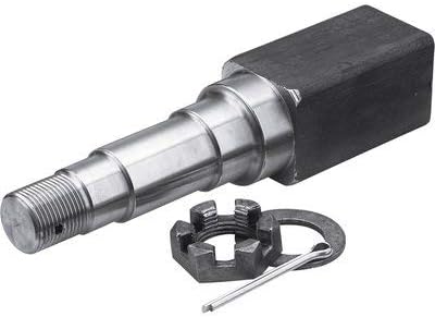
Are there recalls or common issues associated with specific axle spindle models?
Recalls and common issues can occur with specific axle spindle models. Here is a detailed explanation:
Axle spindles are critical components of a vehicle’s suspension system, responsible for supporting the weight of the vehicle and allowing the wheels to rotate. While axle spindle issues are not as common as some other automotive problems, they can still arise in certain situations or with specific models. It’s important to note that recalls and common issues can vary depending on the vehicle make, model, and year. Therefore, it’s essential to consult the manufacturer’s documentation or contact authorized dealerships to obtain the most accurate and up-to-date information regarding recalls or known problems associated with specific axle spindle models.
Recalls are typically issued by vehicle manufacturers or regulatory agencies when a safety-related defect or non-compliance with safety standards is identified in a specific component or vehicle model. When it comes to axle spindles, recalls may be issued if there is evidence of a manufacturing defect, design flaw, or other issues that could compromise the performance, durability, or safety of the axle spindle. Recalls are intended to address these concerns and ensure that affected vehicles are repaired or modified to rectify the problem.
Common issues associated with specific axle spindle models can also arise due to various factors. These issues may be reported by vehicle owners, observed by mechanics or technicians, or identified through data analysis. Common issues can include premature wear, excessive play, bearing failures, or other forms of damage or deterioration that affect the functionality or reliability of the axle spindle.
To determine if there are any recalls or common issues associated with a specific axle spindle model, follow these steps:
- Refer to Manufacturer’s Documentation: Check the manufacturer’s documentation, such as owner’s manuals, maintenance guides, or technical service bulletins. These resources may provide information about known issues, recalls, or recommended maintenance procedures for the axle spindle.
- Contact Authorized Dealerships: Reach out to authorized dealerships or service centers for the vehicle make and model. They often have access to the latest information regarding recalls or common axle spindle issues. Provide them with the specific details of your vehicle, including the make, model, year, and vehicle identification number (VIN) if requested.
- Check Government Recall Databases: Government agencies responsible for vehicle safety, such as the National Highway Traffic Safety Administration (NHTSA) in the United States, maintain databases of recalls. Visit their websites and search for any recalls associated with the specific vehicle make, model, and year.
- Online Forums and Communities: Explore online automotive forums and communities dedicated to the specific vehicle make or model. These platforms often provide valuable insights from owners who may have encountered axle spindle issues or recalls. However, exercise caution and verify the information obtained from such sources, as it may not always be accurate or up to date.
By following these steps, you can gather information about recalls or common issues associated with specific axle spindle models. If a recall or known issue is identified, it’s important to take appropriate action by contacting authorized repair facilities or dealerships to address the problem promptly.
It’s worth noting that not all axle spindle models may have recalls or common issues. Vehicle manufacturers strive to design and produce reliable components, and any potential problems are typically addressed through quality control measures and continuous improvement processes. However, occasional issues can still arise, particularly in specific production runs or under certain operating conditions.
In summary, recalls and common issues can occur with specific axle spindle models. Recalls are typically issued by manufacturers or regulatory agencies to address safety-related defects or non-compliance with safety standards. Common issues can include premature wear, excessive play, bearing failures, or other forms of damage or deterioration. To obtain accurate information about recalls or known issues, refer to the manufacturer’s documentation, contact authorized dealerships, check government recall databases, and explore online forums and communities dedicated to the specific vehicle make or model.
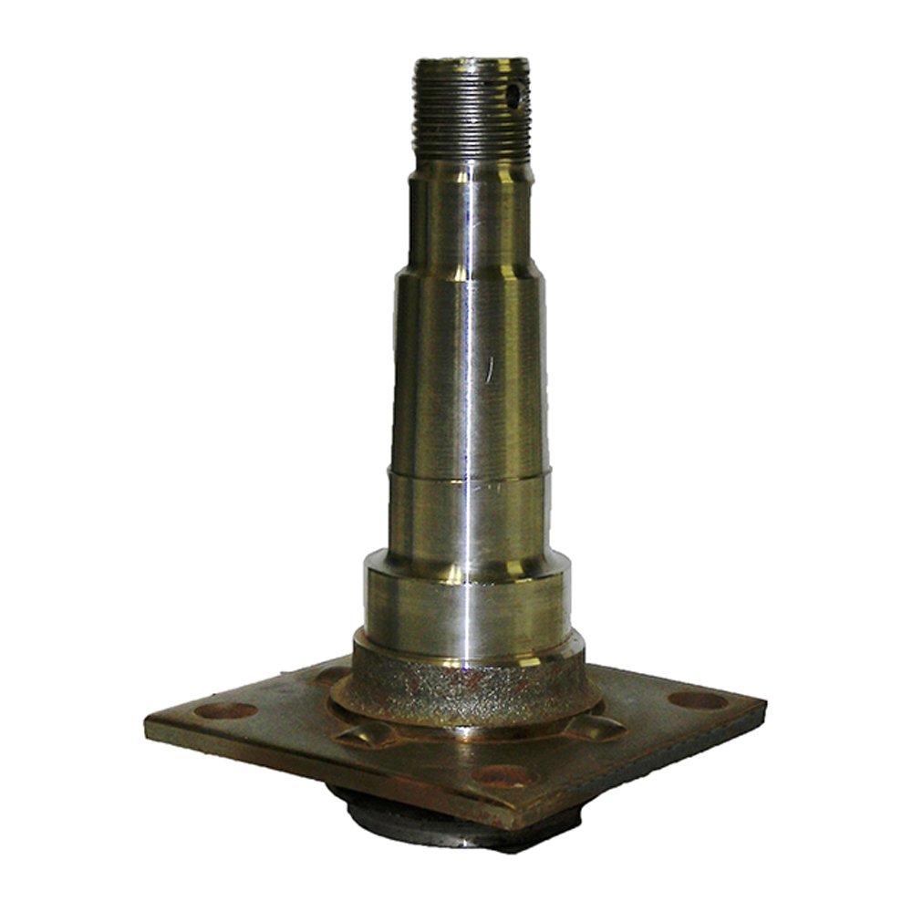
How does a damaged or bent axle spindle impact the performance of a vehicle?
A damaged or bent axle spindle can significantly impact the performance and safety of a vehicle. Here’s a detailed explanation:
When the axle spindle is damaged or bent, it can cause various issues that affect the overall performance and handling of the vehicle. Here are some ways a damaged or bent axle spindle can impact a vehicle:
- Wheel Misalignment: A damaged or bent axle spindle can result in wheel misalignment. This misalignment can cause uneven tire wear, reduced traction, and compromised handling. The vehicle may pull to one side, and the steering may feel unstable or imprecise. Wheel misalignment can also lead to increased rolling resistance, negatively impacting fuel efficiency.
- Vibration and Shaking: A bent axle spindle can cause vibrations and shaking in the vehicle, particularly at higher speeds. The imbalance created by the bent spindle can result in uneven tire rotation and wheel wobbling, leading to an uncomfortable and potentially unsafe driving experience.
- Braking Issues: A damaged axle spindle can affect the performance of the braking system. Uneven wheel rotation caused by a bent spindle can result in inconsistent braking force distribution. This can lead to longer braking distances, reduced braking efficiency, and potentially compromised safety in emergency braking situations.
- Suspension Component Stress: A damaged or bent axle spindle can place excessive stress on other suspension components, such as wheel bearings, control arms, or steering linkage. The misalignment and increased forces can accelerate wear and tear on these components, leading to premature failure and costly repairs.
- Handling and Stability: A compromised axle spindle can negatively impact the vehicle’s handling and stability. It can cause unpredictable steering response, reduced cornering ability, and decreased overall stability during maneuvers. This can increase the risk of loss of control and accidents, especially in emergency or evasive driving situations.
It’s important to address a damaged or bent axle spindle promptly. Continuing to drive with a damaged spindle can exacerbate the issues mentioned above and potentially cause further damage to other components of the suspension system. If you suspect a problem with the axle spindle, it’s recommended to have the vehicle inspected by a qualified mechanic or technician who can accurately diagnose the issue and perform the necessary repairs or replacement.
In summary, a damaged or bent axle spindle can have a significant impact on the performance and safety of a vehicle. It can cause wheel misalignment, vibrations, braking issues, stress on suspension components, and compromised handling and stability. Prompt attention and repair are crucial to ensure the vehicle’s optimal performance and to maintain safety on the road.


editor by CX 2024-02-17
China OEM China OEM Manufacture Metal Processing Working Stainless Steel Auto Car Industry Cylinder Spindle Shaft Thread Connector Pin near me supplier
Product Description
Company Profile
Company Profile
HangZhou Xihu (West Lake) Dis. Gain Machinery Co., Ltd., is a manufacture of precision machining from steel plates, castings & closed die forgings. It is founded in 2571 year, covers a total area of about 2000 square meters.
Around 50 people are employed, including 4 engineers.
The company equipped with 10 oblique CZPT CNC Lathes, 35 normal CNC lathes, 6 machining centers, other milling machines and drilling machines.
The Products cover construction parts, auto parts, medical treatment, aerospace, electronics and other fields, exported to Japan, Israel & other Asian countries and Germany, the United States, Canada & other European and American countries.
Certificated by TS16949 quality management system.
Equipment Introduction
Main facility and working range, inspection equipment as follow
| 4 axles CNC Machine Center | 1000mm*600mm*650mm |
| Oblique Xihu (West Lake) Dis. CNC Machine | max φ800mm max length 700mm Tolerance control within 0.01 One time clamping, high accuracy |
| Turning-milling Compound Machining Center | max φ800mm max length 1000mm |
| Other CNC Lathe | Total 30 sets |
| Inspection Equipment | CMM, Projector, CZPT Scale, Micrometer |
| Profiloscope, Hardness tester and so on |
Oblique Xihu (West Lake) Dis. CNC Lathe
Equipped with 10 sets of oblique CZPT CNC Lathes The maximum diameter can be 400-500 mm Precision can reach 0.01mm
Machining Center
6 sets of 4 axles machining center, max SPEC: 1300*70mm, precision can reach 0.01mm
About Products
Quality Control
We always want to be precise, so check dimensions after each production step. We have senior engineers, skilled CNC operator, professional quality inspector. All this makes sure the final goods are high qualified.
Also can do third parity inspection accoring to customer’s reequirments, such as SGS, TUV, ICAS and so on.
Callipers/Height guage
Thread guage
Go/ no go guage
Inside micrometer
Outside micrometer
Micron scale
CMM
Projector
Micrometer
Profiloscope
Hardness tester
Inspection Process
1. Before machining, the engineer will give away the technology card for each process acc. to drawing for quality control.
2. During the machining, the workers will test the dimensions at each step, then marked in the technology card.
3. When machining finished, the professional testing personnel will do 100% retesting again.
Packing Area
In general, the products will be packed in bubble wrap or separated by plywoods firstly.
Then the wrapped products will be put in the wooden cases (no solid wood), which is allowed for export.
Parts can also be packed acc. to customer’s requirement.
How to Calculate Stiffness, Centering Force, Wear and Fatigue Failure of Spline Couplings
There are various types of spline couplings. These couplings have several important properties. These properties are: Stiffness, Involute splines, Misalignment, Wear and fatigue failure. To understand how these characteristics relate to spline couplings, read this article. It will give you the necessary knowledge to determine which type of coupling best suits your needs. Keeping in mind that spline couplings are usually spherical in shape, they are made of steel.
Involute splines
An effective side interference condition minimizes gear misalignment. When 2 splines are coupled with no spline misalignment, the maximum tensile root stress shifts to the left by 5 mm. A linear lead variation, which results from multiple connections along the length of the spline contact, increases the effective clearance or interference by a given percentage. This type of misalignment is undesirable for coupling high-speed equipment.
Involute splines are often used in gearboxes. These splines transmit high torque, and are better able to distribute load among multiple teeth throughout the coupling circumference. The involute profile and lead errors are related to the spacing between spline teeth and keyways. For coupling applications, industry practices use splines with 25 to 50-percent of spline teeth engaged. This load distribution is more uniform than that of conventional single-key couplings.
To determine the optimal tooth engagement for an involved spline coupling, Xiangzhen Xue and colleagues used a computer model to simulate the stress applied to the splines. The results from this study showed that a “permissible” Ruiz parameter should be used in coupling. By predicting the amount of wear and tear on a crowned spline, the researchers could accurately predict how much damage the components will sustain during the coupling process.
There are several ways to determine the optimal pressure angle for an involute spline. Involute splines are commonly measured using a pressure angle of 30 degrees. Similar to gears, involute splines are typically tested through a measurement over pins. This involves inserting specific-sized wires between gear teeth and measuring the distance between them. This method can tell whether the gear has a proper tooth profile.
The spline system shown in Figure 1 illustrates a vibration model. This simulation allows the user to understand how involute splines are used in coupling. The vibration model shows 4 concentrated mass blocks that represent the prime mover, the internal spline, and the load. It is important to note that the meshing deformation function represents the forces acting on these 3 components.
Stiffness of coupling
The calculation of stiffness of a spline coupling involves the measurement of its tooth engagement. In the following, we analyze the stiffness of a spline coupling with various types of teeth using 2 different methods. Direct inversion and blockwise inversion both reduce CPU time for stiffness calculation. However, they require evaluation submatrices. Here, we discuss the differences between these 2 methods.
The analytical model for spline couplings is derived in the second section. In the third section, the calculation process is explained in detail. We then validate this model against the FE method. Finally, we discuss the influence of stiffness nonlinearity on the rotor dynamics. Finally, we discuss the advantages and disadvantages of each method. We present a simple yet effective method for estimating the lateral stiffness of spline couplings.
The numerical calculation of the spline coupling is based on the semi-analytical spline load distribution model. This method involves refined contact grids and updating the compliance matrix at each iteration. Hence, it consumes significant computational time. Further, it is difficult to apply this method to the dynamic analysis of a rotor. This method has its own limitations and should be used only when the spline coupling is fully investigated.
The meshing force is the force generated by a misaligned spline coupling. It is related to the spline thickness and the transmitting torque of the rotor. The meshing force is also related to the dynamic vibration displacement. The result obtained from the meshing force analysis is given in Figures 7, 8, and 9.
The analysis presented in this paper aims to investigate the stiffness of spline couplings with a misaligned spline. Although the results of previous studies were accurate, some issues remained. For example, the misalignment of the spline may cause contact damages. The aim of this article is to investigate the problems associated with misaligned spline couplings and propose an analytical approach for estimating the contact pressure in a spline connection. We also compare our results to those obtained by pure numerical approaches.
Misalignment
To determine the centering force, the effective pressure angle must be known. Using the effective pressure angle, the centering force is calculated based on the maximum axial and radial loads and updated Dudley misalignment factors. The centering force is the maximum axial force that can be transmitted by friction. Several published misalignment factors are also included in the calculation. A new method is presented in this paper that considers the cam effect in the normal force.
In this new method, the stiffness along the spline joint can be integrated to obtain a global stiffness that is applicable to torsional vibration analysis. The stiffness of bearings can also be calculated at given levels of misalignment, allowing for accurate estimation of bearing dimensions. It is advisable to check the stiffness of bearings at all times to ensure that they are properly sized and aligned.
A misalignment in a spline coupling can result in wear or even failure. This is caused by an incorrectly aligned pitch profile. This problem is often overlooked, as the teeth are in contact throughout the involute profile. This causes the load to not be evenly distributed along the contact line. Consequently, it is important to consider the effect of misalignment on the contact force on the teeth of the spline coupling.
The centre of the male spline in Figure 2 is superposed on the female spline. The alignment meshing distances are also identical. Hence, the meshing force curves will change according to the dynamic vibration displacement. It is necessary to know the parameters of a spline coupling before implementing it. In this paper, the model for misalignment is presented for spline couplings and the related parameters.
Using a self-made spline coupling test rig, the effects of misalignment on a spline coupling are studied. In contrast to the typical spline coupling, misalignment in a spline coupling causes fretting wear at a specific position on the tooth surface. This is a leading cause of failure in these types of couplings.
Wear and fatigue failure
The failure of a spline coupling due to wear and fatigue is determined by the first occurrence of tooth wear and shaft misalignment. Standard design methods do not account for wear damage and assess the fatigue life with big approximations. Experimental investigations have been conducted to assess wear and fatigue damage in spline couplings. The tests were conducted on a dedicated test rig and special device connected to a standard fatigue machine. The working parameters such as torque, misalignment angle, and axial distance have been varied in order to measure fatigue damage. Over dimensioning has also been assessed.
During fatigue and wear, mechanical sliding takes place between the external and internal splines and results in catastrophic failure. The lack of literature on the wear and fatigue of spline couplings in aero-engines may be due to the lack of data on the coupling’s application. Wear and fatigue failure in splines depends on a number of factors, including the material pair, geometry, and lubrication conditions.
The analysis of spline couplings shows that over-dimensioning is common and leads to different damages in the system. Some of the major damages are wear, fretting, corrosion, and teeth fatigue. Noise problems have also been observed in industrial settings. However, it is difficult to evaluate the contact behavior of spline couplings, and numerical simulations are often hampered by the use of specific codes and the boundary element method.
The failure of a spline gear coupling was caused by fatigue, and the fracture initiated at the bottom corner radius of the keyway. The keyway and splines had been overloaded beyond their yield strength, and significant yielding was observed in the spline gear teeth. A fracture ring of non-standard alloy steel exhibited a sharp corner radius, which was a significant stress raiser.
Several components were studied to determine their life span. These components include the spline shaft, the sealing bolt, and the graphite ring. Each of these components has its own set of design parameters. However, there are similarities in the distributions of these components. Wear and fatigue failure of spline couplings can be attributed to a combination of the 3 factors. A failure mode is often defined as a non-linear distribution of stresses and strains.


China Standard Precison Machining Metal Stainless Steel OEM CNC Turning Milling Auto Car Machinery Shaft Pin Bushing Spindle CZPT Clamp Cylinder Fittings Spare Parts wholesaler
Product Description
Company Profile
Company Profile
HangZhou Xihu (West Lake) Dis. Gain Machinery Co., Ltd., is a manufacture of precision machining from steel plates, castings & closed die forgings. It is founded in 2571 year, covers a total area of about 2000 square meters.
Around 50 people are employed, including 4 engineers.
The company equipped with 10 oblique CZPT CNC Lathes, 35 normal CNC lathes, 6 machining centers, other milling machines and drilling machines.
The Products cover construction parts, auto parts, medical treatment, aerospace, electronics and other fields, exported to Japan, Israel & other Asian countries and Germany, the United States, Canada & other European and American countries.
Certificated by TS16949 quality management system.
Equipment Introduction
Main facility and working range, inspection equipment as follow
| 4 axles CNC Machine Center | 1000mm*600mm*650mm |
| Oblique Xihu (West Lake) Dis. CNC Machine | max φ800mm max length 700mm Tolerance control within 0.01 One time clamping, high accuracy |
| Turning-milling Compound Machining Center | max φ800mm max length 1000mm |
| Other CNC Lathe | Total 30 sets |
| Inspection Equipment | CMM, Projector, CZPT Scale, Micrometer |
| Profiloscope, Hardness tester and so on |
Oblique Xihu (West Lake) Dis. CNC Lathe
Equipped with 10 sets of oblique CZPT CNC Lathes The maximum diameter can be 400-500 mm Precision can reach 0.01mm
Machining Center
6 sets of 4 axles machining center, max SPEC: 1300*70mm, precision can reach 0.01mm
About Products
Quality Control
We always want to be precise, so check dimensions after each production step. We have senior engineers, skilled CNC operator, professional quality inspector. All this makes sure the final goods are high qualified.
Also can do third parity inspection accoring to customer’s reequirments, such as SGS, TUV, ICAS and so on.
Callipers/Height guage
Thread guage
Go/ no go guage
Inside micrometer
Outside micrometer
Micron scale
CMM
Projector
Micrometer
Profiloscope
Hardness tester
Inspection Process
1. Before machining, the engineer will give away the technology card for each process acc. to drawing for quality control.
2. During the machining, the workers will test the dimensions at each step, then marked in the technology card.
3. When machining finished, the professional testing personnel will do 100% retesting again.
Packing Area
In general, the products will be packed in bubble wrap or separated by plywoods firstly.
Then the wrapped products will be put in the wooden cases (no solid wood), which is allowed for export.
Parts can also be packed acc. to customer’s requirement.
The Benefits of Spline Couplings for Disc Brake Mounting Interfaces
Spline couplings are commonly used for securing disc brake mounting interfaces. Spline couplings are often used in high-performance vehicles, aeronautics, and many other applications. However, the mechanical benefits of splines are not immediately obvious. Listed below are the benefits of spline couplings. We’ll discuss what these advantages mean for you. Read on to discover how these couplings work.
Disc brake mounting interfaces are splined
There are 2 common disc brake mounting interfaces – splined and six-bolt. Splined rotors fit on splined hubs; six-bolt rotors will need an adapter to fit on six-bolt hubs. The six-bolt method is easier to maintain and may be preferred by many cyclists. If you’re thinking of installing a disc brake system, it is important to know how to choose the right splined and center lock interfaces.
Aerospace applications
The splines used for spline coupling in aircraft are highly complex. While some previous researches have addressed the design of splines, few publications have tackled the problem of misaligned spline coupling. Nevertheless, the accurate results we obtained were obtained using dedicated simulation tools, which are not commercially available. Nevertheless, such tools can provide a useful reference for our approach. It would be beneficial if designers could use simple tools for evaluating contact pressure peaks. Our analytical approach makes it possible to find answers to such questions.
The design of a spline coupling for aerospace applications must be accurate to minimize weight and prevent failure mechanisms. In addition to weight reduction, it is necessary to minimize fretting fatigue. The pressure distribution on the spline coupling teeth is a significant factor in determining its fretting fatigue. Therefore, we use analytical and experimental methods to examine the contact pressure distribution in the axial direction of spline couplings.
The teeth of a spline coupling can be categorized by the type of engagement they provide. This study investigates the position of resultant contact forces in the teeth of a spline coupling when applied to pitch diameter. Using FEM models, numerical results are generated for nominal and parallel offset misalignments. The axial tooth profile determines the behavior of the coupling component and its ability to resist wear. Angular misalignment is also a concern, causing misalignment.
In order to assess wear damage of a spline coupling, we must take into consideration the impact of fretting on the components. This wear is caused by relative motion between the teeth that engage them. The misalignment may be caused by vibrations, cyclical tooth deflection, or angular misalignment. The result of this analysis may help designers improve their spline coupling designs and develop improved performance.
CZPT polyimide, an abrasion-resistant polymer, is a popular choice for high-temperature spline couplings. This material reduces friction and wear, provides a low friction surface, and has a low wear rate. Furthermore, it offers up to 50 times the life of metal on metal spline connections. For these reasons, it is important to choose the right material for your spline coupling.
High-performance vehicles
A spline coupler is a device used to connect splined shafts. A typical spline coupler resembles a short pipe with splines on either end. There are 2 basic types of spline coupling: single and dual spline. One type attaches to a drive shaft, while the other attaches to the gearbox. While spline couplings are typically used in racing, they’re also used for performance problems.
The key challenge in spline couplings is to determine the optimal dimension of spline joints. This is difficult because no commercial codes allow the simulation of misaligned joints, which can destroy components. This article presents analytical approaches to estimating contact pressures in spline connections. The results are comparable with numerical approaches but require special codes to accurately model the coupling operation. This research highlights several important issues and aims to make the application of spline couplings in high-performance vehicles easier.
The stiffness of spline assemblies can be calculated using tooth-like structures. Such splines can be incorporated into the spline joint to produce global stiffness for torsional vibration analysis. Bearing reactions are calculated for a certain level of misalignment. This information can be used to design bearing dimensions and correct misalignment. There are 3 types of spline couplings.
Major diameter fit splines are made with tightly controlled outside diameters. This close fit provides concentricity transfer from the male to the female spline. The teeth of the male spline usually have chamfered tips and clearance with fillet radii. These splines are often manufactured from billet steel or aluminum. These materials are renowned for their strength and uniform grain created by the forging process. ANSI and DIN design manuals define classes of fit.
Disc brake mounting interfaces
A spline coupling for disc brake mounting interfaces is a type of hub-to-brake-disc mount. It is a highly durable coupling mechanism that reduces heat transfer from the disc to the axle hub. The mounting arrangement also isolates the axle hub from direct contact with the disc. It is also designed to minimize the amount of vehicle downtime and maintenance required to maintain proper alignment.
Disc brakes typically have substantial metal-to-metal contact with axle hub splines. The discs are held in place on the hub by intermediate inserts. This metal-to-metal contact also aids in the transfer of brake heat from the brake disc to the axle hub. Spline coupling for disc brake mounting interfaces comprises a mounting ring that is either a threaded or non-threaded spline.
During drag brake experiments, perforated friction blocks filled with various additive materials are introduced. The materials included include Cu-based powder metallurgy material, a composite material, and a Mn-Cu damping alloy. The filling material affects the braking interface’s wear behavior and friction-induced vibration characteristics. Different filling materials produce different types of wear debris and have different wear evolutions. They also differ in their surface morphology.
Disc brake couplings are usually made of 2 different types. The plain and HD versions are interchangeable. The plain version is the simplest to install, while the HD version has multiple components. The two-piece couplings are often installed at the same time, but with different mounting interfaces. You should make sure to purchase the appropriate coupling for your vehicle. These interfaces are a vital component of your vehicle and must be installed correctly for proper operation.
Disc brakes use disc-to-hub elements that help locate the forces and displace them to the rim. These elements are typically made of stainless steel, which increases the cost of manufacturing the disc brake mounting interface. Despite their benefits, however, the high braking force loads they endure are hard on the materials. Moreover, excessive heat transferred to the intermediate elements can adversely affect the fatigue life and long-term strength of the brake system.
China Professional China OEM Metal Manufacturer Precision Machining CNC Turning Milling Auto Car Machinery Shaft Axle Cylinder Spindle Stainless Bolt Screw Nut Locker Step Pin with Great quality
Product Description
Company Profile
Company Profile
HangZhou Xihu (West Lake) Dis. Gain Machinery Co., Ltd., is a manufacture of precision machining from steel plates, castings & closed die forgings. It is founded in 2571 year, covers a total area of about 2000 square meters.
Around 50 people are employed, including 4 engineers.
The company equipped with 10 oblique CZPT CNC Lathes, 35 normal CNC lathes, 6 machining centers, other milling machines and drilling machines.
The Products cover construction parts, auto parts, medical treatment, aerospace, electronics and other fields, exported to Japan, Israel & other Asian countries and Germany, the United States, Canada & other European and American countries.
Certificated by TS16949 quality management system.
Equipment Introduction
Main facility and working range, inspection equipment as follow
| 4 axles CNC Machine Center | 1000mm*600mm*650mm |
| Oblique Xihu (West Lake) Dis. CNC Machine | max φ800mm max length 700mm Tolerance control within 0.01 One time clamping, high accuracy |
| Turning-milling Compound Machining Center | max φ800mm max length 1000mm |
| Other CNC Lathe | Total 30 sets |
| Inspection Equipment | CMM, Projector, CZPT Scale, Micrometer |
| Profiloscope, Hardness tester and so on |
Oblique Xihu (West Lake) Dis. CNC Lathe
Equipped with 10 sets of oblique CZPT CNC Lathes The maximum diameter can be 400-500 mm Precision can reach 0.01mm
Machining Center
6 sets of 4 axles machining center, max SPEC: 1300*70mm, precision can reach 0.01mm
About Products
Quality Control
We always want to be precise, so check dimensions after each production step. We have senior engineers, skilled CNC operator, professional quality inspector. All this makes sure the final goods are high qualified.
Also can do third parity inspection accoring to customer’s reequirments, such as SGS, TUV, ICAS and so on.
Callipers/Height guage
Thread guage
Go/ no go guage
Inside micrometer
Outside micrometer
Micron scale
CMM
Projector
Micrometer
Profiloscope
Hardness tester
Inspection Process
1. Before machining, the engineer will give away the technology card for each process acc. to drawing for quality control.
2. During the machining, the workers will test the dimensions at each step, then marked in the technology card.
3. When machining finished, the professional testing personnel will do 100% retesting again.
Packing Area
In general, the products will be packed in bubble wrap or separated by plywoods firstly.
Then the wrapped products will be put in the wooden cases (no solid wood), which is allowed for export.
Parts can also be packed acc. to customer’s requirement.
Types of Splines
There are 4 types of splines: Involute, Parallel key, helical, and ball. Learn about their characteristics. And, if you’re not sure what they are, you can always request a quotation. These splines are commonly used for building special machinery, repair jobs, and other applications. The CZPT Manufacturing Company manufactures these shafts. It is a specialty manufacturer and we welcome your business.
Involute splines
The involute spline provides a more rigid and durable structure, and is available in a variety of diameters and spline counts. Generally, steel, carbon steel, or titanium are used as raw materials. Other materials, such as carbon fiber, may be suitable. However, titanium can be difficult to produce, so some manufacturers make splines using other constituents.
When splines are used in shafts, they prevent parts from separating during operation. These features make them an ideal choice for securing mechanical assemblies. Splines with inward-curving grooves do not have sharp corners and are therefore less likely to break or separate while they are in operation. These properties help them to withstand high-speed operations, such as braking, accelerating, and reversing.
A male spline is fitted with an externally-oriented face, and a female spline is inserted through the center. The teeth of the male spline typically have chamfered tips to provide clearance with the transition area. The radii and width of the teeth of a male spline are typically larger than those of a female spline. These specifications are specified in ANSI or DIN design manuals.
The effective tooth thickness of a spline depends on the involute profile error and the lead error. Also, the spacing of the spline teeth and keyways can affect the effective tooth thickness. Involute splines in a splined shaft are designed so that at least 25 percent of the spline teeth engage during coupling, which results in a uniform distribution of load and wear on the spline.
Parallel key splines
A parallel splined shaft has a helix of equal-sized grooves around its circumference. These grooves are generally parallel or involute. Splines minimize stress concentrations in stationary joints and allow linear and rotary motion. Splines may be cut or cold-rolled. Cold-rolled splines have more strength than cut spines and are often used in applications that require high strength, accuracy, and a smooth surface.
A parallel key splined shaft features grooves and keys that are parallel to the axis of the shaft. This design is best suited for applications where load bearing is a primary concern and a smooth motion is needed. A parallel key splined shaft can be made from alloy steels, which are iron-based alloys that may also contain chromium, nickel, molybdenum, copper, or other alloying materials.
A splined shaft can be used to transmit torque and provide anti-rotation when operating as a linear guide. These shafts have square profiles that match up with grooves in a mating piece and transmit torque and rotation. They can also be easily changed in length, and are commonly used in aerospace. Its reliability and fatigue life make it an excellent choice for many applications.
The main difference between a parallel key splined shaft and a keyed shaft is that the former offers more flexibility. They lack slots, which reduce torque-transmitting capacity. Splines offer equal load distribution along the gear teeth, which translates into a longer fatigue life for the shaft. In agricultural applications, shaft life is essential. Agricultural equipment, for example, requires the ability to function at high speeds for extended periods of time.
Involute helical splines
Involute splines are a common design for splined shafts. They are the most commonly used type of splined shaft and feature equal spacing among their teeth. The teeth of this design are also shorter than those of the parallel spline shaft, reducing stress concentration. These splines can be used to transmit power to floating or permanently fixed gears, and reduce stress concentrations in the stationary joint. Involute splines are the most common type of splined shaft, and are widely used for a variety of applications in automotive, machine tools, and more.
Involute helical spline shafts are ideal for applications involving axial motion and rotation. They allow for face coupling engagement and disengagement. This design also allows for a larger diameter than a parallel spline shaft. The result is a highly efficient gearbox. Besides being durable, splines can also be used for other applications involving torque and energy transfer.
A new statistical model can be used to determine the number of teeth that engage for a given load. These splines are characterized by a tight fit at the major diameters, thereby transferring concentricity from the shaft to the female spline. A male spline has chamfered tips for clearance with the transition area. ANSI and DIN design manuals specify the different classes of fit.
The design of involute helical splines is similar to that of gears, and their ridges or teeth are matched with the corresponding grooves in a mating piece. It enables torque and rotation to be transferred to a mate piece while maintaining alignment of the 2 components. Different types of splines are used in different applications. Different splines can have different levels of tooth height.
Involute ball splines
When splines are used, they allow the shaft and hub to engage evenly over the shaft’s entire circumference. Because the teeth are evenly spaced, the load that they can transfer is uniform and their position is always the same regardless of shaft length. Whether the shaft is used to transmit torque or to transmit power, splines are a great choice. They provide maximum strength and allow for linear or rotary motion.
There are 3 basic types of splines: helical, crown, and ball. Crown splines feature equally spaced grooves. Crown splines feature involute sides and parallel sides. Helical splines use involute teeth and are often used in small diameter shafts. Ball splines contain a ball bearing inside the splined shaft to facilitate rotary motion and minimize stress concentration in stationary joints.
The 2 types of splines are classified under the ANSI classes of fit. Fillet root splines have teeth that mesh along the longitudinal axis of rotation. Flat root splines have similar teeth, but are intended to optimize strength for short-term use. Both types of splines are important for ensuring the shaft aligns properly and is not misaligned.
The friction coefficient of the hub is a complex process. When the hub is off-center, the center moves in predictable but irregular motion. Moreover, when the shaft is centered, the center may oscillate between being centered and being off-center. To compensate for this, the torque must be adequate to keep the shaft in its axis during all rotation angles. While straight-sided splines provide similar centering, they have lower misalignment load factors.
Keyed shafts
Essentially, splined shafts have teeth or ridges that fit together to transfer torque. Because splines are not as tall as involute gears, they offer uniform torque transfer. Additionally, they provide the opportunity for torque and rotational changes and improve wear resistance. In addition to their durability, splined shafts are popular in the aerospace industry and provide increased reliability and fatigue life.
Keyed shafts are available in different materials, lengths, and diameters. When used in high-power drive applications, they offer higher torque and rotational speeds. The higher torque they produce helps them deliver power to the gearbox. However, they are not as durable as splined shafts, which is why the latter is usually preferred in these applications. And while they’re more expensive, they’re equally effective when it comes to torque delivery.
Parallel keyed shafts have separate profiles and ridges and are used in applications requiring accuracy and precision. Keyed shafts with rolled splines are 35% stronger than cut splines and are used where precision is essential. These splines also have a smooth finish, which can make them a good choice for precision applications. They also work well with gears and other mechanical systems that require accurate torque transfer.
Carbon steel is another material used for splined shafts. Carbon steel is known for its malleability, and its shallow carbon content helps create reliable motion. However, if you’re looking for something more durable, consider ferrous steel. This type contains metals such as nickel, chromium, and molybdenum. And it’s important to remember that carbon steel is not the only material to consider.