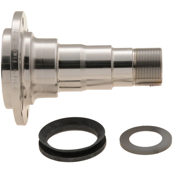
Product Description
Eliminator Torsion Axle Replacement Spindle
| Part No. | A | B | C | D | E | F | G |
| HTA100 | 1.75″ | 1.38″ | 1.06″ | 1.72″ | 8.10″ | 4.11″ | 0.91″ |
Includes:
- (2) Axle nut
- (2) 1″ x 1 3/4″ Washer Non-Plate
- (2) Cotter pin
- (1) Spindle with grease zerk
HangZhou CZPT Machinery Co., Ltd is a professional manufacturer of trailer parts in HangZhou, ZHangZhoug Province, China since 2016.
We can produce many trailer parts & accessories as follows: Towbars, axles, brake drums, hubs, brake disc, bearings, springs and springs and suspension kits, couplings, mudguards, U-Bolts, Jockey Wheels, keel rollers and brackets, wobble roller, wheel spacer, equalizers and all accessories related to trailers.
If you can send me the drawings or specifications of the trailer parts, mechanical parts and wheels, we can give you our price.
Welcome to enquiry and email me,thanks!
Q1: Do you have factory?
A: Yes, we have our own factory, own engineers, we can meet custom’s unique requirement.
Q2: Can I have a sample order?
A: Yes, welcome sample order to test and check quality. Mixed samples are acceptable.
Q3: It’s OK to print my logo on your product?
A: Yes, we can according to your exact requirement.
Q4:How do you ship the goods and how long does it take arrive?
A: We usually shipped by DHL, UPS, FedEx, it usually takes 3-5 days to arrive. Airline and sea shipping also optional.
Q5: What is your advantages?
A: We are professional supplier for more than 10 years, we always put the quality and price at the first place. At the same time, our products are exported to various countries, we have full experience to solve thorny problems.
1-Welcome OEM
- You can use your own brands or ours, if you use our brand, our professional team will help you design the packing.
2-Our service
- You inquiry related to our products or prices will be replied in 24 hours.
- Well-trained and experienced staffs to answer all your enquirys in fluent English.
- Protection of your sales area, ideas of your design and all your private information.
- We have a QC team, every product will be checked by them before packed.
3-Welcome to visit
- When you come to our company visit us, we will arrange a car for picking up and help you book hotel. If you want to visit the local scenic spot, our colleague will accompany you.
4-Warranty
- Customer should be provide the video and the pictures for the problem products.
- Products returned within the warranty period must bear product number & date code.
5-After service
- In production and after delivery, we will track on time and tell you goods situation.
- When the goods arrived, if you find any design and quality questions, or difference from your samples, please feel free to contact us, we will find the question and solve it with you.
/* March 10, 2571 17:59:20 */!function(){function s(e,r){var a,o={};try{e&&e.split(“,”).forEach(function(e,t){e&&(a=e.match(/(.*?):(.*)$/))&&1
| Condition: | New |
|---|---|
| Axle Number: | 1 |
| Application: | Trailer |
| Samples: |
US$ 10/Piece
1 Piece(Min.Order) | Order Sample |
|---|
| Customization: |
Available
| Customized Request |
|---|
.shipping-cost-tm .tm-status-off{background: none;padding:0;color: #1470cc}
|
Shipping Cost:
Estimated freight per unit. |
about shipping cost and estimated delivery time. |
|---|
| Payment Method: |
|
|---|---|
|
Initial Payment Full Payment |
| Currency: | US$ |
|---|
| Return&refunds: | You can apply for a refund up to 30 days after receipt of the products. |
|---|

What is the relationship between the axle spindle and the wheel bearing in a vehicle?
In a vehicle, the axle spindle and the wheel bearing are two interconnected components that work together to allow the wheel to rotate smoothly and support the vehicle’s weight. Here’s a detailed explanation of their relationship:
The axle spindle is a key part of the vehicle’s suspension system, specifically in the axle assembly. It is a shaft-like component that protrudes from the axle housing and provides support for the wheel assembly. The spindle is typically located at the center of the wheel hub and serves as a mounting point for various components, including the wheel bearing.
The wheel bearing, on the other hand, is a set of precision-engineered bearings that are usually housed within a hub assembly. It is responsible for reducing friction and facilitating the smooth rotation of the wheel. The wheel bearing allows the wheel to spin freely while supporting the weight of the vehicle and enduring the forces generated during acceleration, braking, and cornering.
The relationship between the axle spindle and the wheel bearing is one of integration and mutual dependency. The axle spindle provides the structural support and attachment point for the wheel bearing assembly. The wheel bearing, in turn, enables the wheel to rotate with minimal friction and provides load-bearing capability.
When the vehicle is in motion, the axle spindle transfers the weight of the vehicle and the forces generated by the road surface to the wheel bearing. The wheel bearing, with its lubricated bearings and races, allows the wheel to rotate smoothly and evenly distribute the applied forces. This relationship ensures that the wheel assembly operates effectively, providing stability, control, and a comfortable ride.
Over time, the wheel bearing may experience wear and tear due to continuous use, exposure to contaminants, or lack of proper maintenance. When a wheel bearing becomes worn or damaged, it can lead to various symptoms such as excessive noise, vibration, uneven tire wear, or even wheel detachment. In such cases, it is necessary to replace the wheel bearing assembly, which often involves disassembling the axle spindle to access and replace the bearing.
It’s important to note that the specific design and configuration of the axle spindle and wheel bearing can vary between different vehicle models and manufacturers. Some vehicles may have integrated wheel bearing and hub assemblies, while others may have separate components that are assembled onto the spindle. It is recommended to consult the vehicle’s repair manual or seek professional assistance for specific instructions and procedures related to your vehicle.
In summary, the axle spindle and the wheel bearing have a close relationship in a vehicle’s suspension system. The axle spindle provides structural support and serves as the mounting point for the wheel bearing assembly. The wheel bearing, in turn, allows the wheel to rotate smoothly, supports the vehicle’s weight, and helps absorb the forces generated during driving. Understanding this relationship is important for proper maintenance, repair, and replacement of the wheel bearing assembly.
Can axle spindles be upgraded for improved performance, and if so, what are the options?
Axle spindles can be upgraded to improve the performance of a vehicle, particularly in applications where higher strength, durability, or enhanced capabilities are desired. Upgrading axle spindles can provide benefits such as increased load capacity, improved off-road capability, or enhanced towing capabilities. Here are some options for upgrading axle spindles:
- High-Strength Axle Spindles: One option is to replace the stock axle spindles with high-strength counterparts. High-strength axle spindles are typically made from stronger materials or feature reinforced designs to handle heavier loads or harsher conditions. These upgraded spindles can enhance the overall strength and durability of the axle assembly.
- Performance Axle Spindles: Performance-oriented axle spindles are designed to improve the handling and responsiveness of the vehicle. These spindles may feature optimized geometry, reduced weight, or enhanced stiffness to provide better cornering abilities, reduced body roll, or improved steering precision. Performance axle spindles are commonly used in applications such as racing or high-performance vehicles.
- Off-Road Axle Spindles: Off-road enthusiasts may opt for axle spindles specifically designed for rugged terrains. These spindles often have increased ground clearance, improved articulation, or additional reinforcement to withstand the demands of off-road driving. They can enhance the vehicle’s off-road capability, allowing for traversing challenging obstacles and rough terrain more effectively.
- Towing and Hauling Axle Spindles: Upgraded axle spindles for towing or hauling purposes are engineered to handle heavier loads and provide increased stability. These spindles may have reinforced construction, larger bearings, or specialized features such as integrated trailer brake connections. Upgrading to towing or hauling axle spindles can enhance the vehicle’s towing capacity and improve overall towing performance.
- Custom Axle Spindles: In some cases, custom axle spindles can be fabricated or modified to meet specific performance requirements. This option is typically utilized in specialized vehicle applications or when specific performance goals cannot be achieved with off-the-shelf upgrades. Custom axle spindles allow for tailored solutions that can address unique needs and performance objectives.
When considering axle spindle upgrades, it is essential to ensure compatibility with other components of the axle assembly, such as bearings, hubs, and brakes. Upgrades may also require modifications to other parts of the vehicle, such as suspension systems or steering components, to optimize performance and maintain overall safety and reliability.
It is recommended to consult with knowledgeable professionals, such as experienced mechanics, axle specialists, or vehicle customization experts, to determine the most suitable upgrade options for your specific vehicle and performance goals. They can provide guidance on selecting the appropriate axle spindle upgrades and ensure proper installation and integration into the vehicle’s overall system.
Can a DIY enthusiast replace a damaged axle spindle, and what are the steps involved?
Replacing a damaged axle spindle is a complex mechanical task that requires advanced knowledge and specialized tools. It is generally recommended to seek the assistance of a professional mechanic or technician for such a repair. However, if you have the necessary expertise, experience, and access to the appropriate tools, it may be possible for a skilled DIY enthusiast to replace a damaged axle spindle. Here are the general steps involved in replacing an axle spindle:
Note: The following steps provide a general outline of the process, but it’s important to consult the specific repair manual for your vehicle and follow the manufacturer’s instructions.
- Preparation: Begin by ensuring that you have the correct replacement axle spindle that matches the specifications of your vehicle. Gather all the necessary tools and equipment required for the job, including a hydraulic jack, jack stands, socket set, wrenches, pry bar, torque wrench, and any specialized tools mentioned in the repair manual.
- Vehicle Preparation: Park the vehicle on a level surface and engage the parking brake. If the axle spindle to be replaced is on the front axle, turn the steering wheel to the straight-ahead position. If it’s on the rear axle, chock the front wheels to prevent the vehicle from rolling.
- Suspension Disassembly: Depending on the vehicle’s design, you may need to remove certain components to access the axle spindle. This can include removing the wheel, brake caliper, brake rotor or drum, tie rod ends, ball joints, axle shafts, and any other components obstructing the spindle’s removal. Follow the repair manual instructions for proper disassembly.
- Axle Spindle Removal: Once the suspension components are removed, you can proceed with removing the damaged axle spindle. This typically involves disconnecting any remaining attachments, such as mounting bolts or fasteners, and carefully maneuvering the spindle out of its housing. Take care not to damage surrounding components or disturb other parts of the suspension system.
- Axle Spindle Installation: Install the replacement axle spindle by following the reverse order of the removal steps. Carefully position the spindle back into its housing, ensuring proper alignment. Reattach any fasteners or mounting bolts according to the specified torque values. Take care to follow the manufacturer’s instructions for any specific procedures or considerations during installation.
- Suspension Reassembly: Reinstall all the components that were removed during the disassembly process, including brake calipers, rotors or drums, tie rod ends, ball joints, axle shafts, and any other relevant parts. Ensure that all connections are secure and torqued to the specified values.
- Final Checks: Double-check all the connections, fasteners, and components to ensure everything is properly reassembled. Confirm that the axle spindle is securely in place and aligned correctly. Before lowering the vehicle, perform a thorough inspection of the suspension system to ensure there are no loose or forgotten components.
- Testing and Alignment: Once the replacement axle spindle is installed, it’s important to have the vehicle’s alignment checked and adjusted by a professional. Improper alignment can lead to uneven tire wear, handling issues, and compromised safety. Schedule a visit to an alignment specialist to ensure the vehicle’s alignment is within the recommended specifications.
It’s crucial to note that replacing an axle spindle involves working with critical components of the vehicle’s suspension and steering systems. Misinstallation or improper assembly can lead to severe safety risks and further damage to the vehicle. If you are unsure or lack the experience and expertise, it is strongly recommended to entrust the task to a qualified professional mechanic or technician.
In summary, while a skilled DIY enthusiast may be able to replace a damaged axle spindle, it is a complex task that requires advanced knowledge, experience, and specialized tools. It’s important to follow the manufacturer’s instructions, consult the repair manual for your specific vehicle, and exercise caution throughout the process. If in doubt, it’s best to seek professional assistance to ensure the job is done safely and correctly.


editor by CX 2024-01-12
China Custom Forging Parts for Machine Tool Screw Stem near me factory
Product Description
Your customized parts,Customized solutions
Company profiles
We established in 2571 year, named Xihu (West Lake) Dis. Tongyong Machinery Company. In 2019 renamed HangZhou Hejess Machinery Co.,Ltd and established new plants.
We are mainly engaged in the designing and manufacturing of steel machinery components and non-standard machinery parts, including shafts, flange, gears, rings, sheaves, couplings, bearing supports, and forgings etc.
Production Parameter
- Material: Alloy steel,Carbon steel,Carburizing steel,Quenched and tempered steel
- Heat treatment: Normalizing,Annealing,Quenching&Tempering,Surface Quenching, Induction hardening
- Machining: CNC Turning,CNC Milling,CNC Boring,CNC Grinding,CNC Drilling
- Gear Machining: Gear Hobbing,Gear Milling,CNC Gear Milling,Gear Cutting,Spiral gear cutting,
- Gear Cutting
- Inspection: Chemical Composition Test,Ultrasonic Test,Penetration Test,Radiographic Test,
Magnetic Test,Tensile Strength Test,Impact Test,Hardness Test,Dimension Test.
We can provide forging from 1kg to 5Ton. And make precison machining. Also have welding and assembly capabilities.
Quality Control
Product quality is what we are paying great attention to all the time. Each product is produced under careful control at every process and inspected by experienced engineers strictly according to the related standards and customer requirements, ensuring the super performance of our goods when arrive at customer.
Ø Production Flow Chart
1, Order Analyzing
Know requirements of raw material, chemical composition, Mechanical properties.
Analyzing how to forging and how to make heat treatment.
2, Raw material.
Use which raw material, plate, round bar, steel ingot.
According your parts, choose the best cost performance one.
If you required special material, will customized from steel factory.
Customized raw material according your requirments.
3, Forging
Make forging process chart and forging form
Make forging drawing
Make 3D drawing
Make forging mould
4, Pre – forging
5, Finish – forging
Natural gas heating furnaces are monitored and controlled by computer programs to ensure precise heating within set time and temperature range as required.
A broad range of forging equipment,including friction press, hudraulic hammer, forging hammers.With the aids od intelligent software,proper deformation,forging ration,ingot size and weight,forging tooling and equipment will be determined to ensure the wrought structure through hout and sound quality.
6, Pre- machining
7, Make UT (ultrasonic) inspection.
8, Make heat treatment
9, Inspect hardness and mechanical properties.
10, Make precision machining / finished machining.
Use CNC machining center, CNC milling, CNC boring, CNC grinding
11, Inspect dimenssions.
12, Protecting and packing.
Main market : America, Australia, Malaysia,Israel,Britain, Russia,Canada, ect.
Services : The services we can provide are : FOB, CIF, DAP. Only give me the drawings and requirements, you will receive the goods at your home.
Wehas accumulated rich knowledge and experience in the producing and exporting. Familar every process, when metting problems, be able to find a solution timely.
Excellent service attitude, fast reaction speed, on-time delivery, consciousness of responsibility and flexibility is what we are practicing from the very beginning, combining with high credit, competitive price, close interaction with customer and innovative way of working, make us win more and more business and excellent customer satisfaction.
To choose us, HangZhou CZPT Machinery, as your business partner, never will you find you are wrong!
PRODUCTION DETAILS
| Technology : | Free forging / Open forging / Die forging / closed forging / Impression die forging / Flashless forging / multi-ram forging / multidirectional die forging / precision forging / croe forging / combination forging / extrusion forging / roll forging / reducer rolling / ring rolling / open die forging / flat die forging / loose tooling forging |
| Material Standard : | ISO / DIN / W-Nr / BS / EN / ASTM / ASME / AISI / UNS / SAE / JIS / SS/ NF / GOST / OCT / GB |
| Material Type: | Austenilic Ni-Cr Stainless Steel / Austenitic Alloy Steel / Austenitic Stainless Stee / Axle Shaft Steel / Bar Steel / Bearing Steel / Bolting Steel / Carbon And Low-Alloy Steel Vessels / Carbon Steel / Carbon Tool Steel / Carbon-Containing Alloy Steel / Case-Hardened Steel / Cast Steel / Cast-Steel Pipe / Centrifugal Steel / Centrifuge(D) Steel / Channel Steel / Chilled Hardened Steel / Chrome Hardened Steel / Chrome-Carbon Steel / Chrome-Molybdenum Steel / Chrome-Nickel Steel / Closed Die Steel / Coating Steel Pipe / Die Steel / Drawing Steel / Extra-High-Tensile Steel / Fabricated Steel / Ferritic Stainless Steel / Ferritic Steel / Figured Steel / Fine Steel / Flange Steel / Groove Steel / Hard Alloy Steel / High Alloy Steel / High Boron Steel / High Carbon Steel / High Chrome Alloy Steel / High Manganese Steel / High Nickel-Chrome Steel |
Show the production process as below photos:
Our Products Catalogue
| Products Catalogue | |||||
| Item | Application | Technical | Material | Picture | Market |
| 1 | Lift Rod | Forging – heat treatment – CNC machining – CNC Grinding | Alloy steel | Australia | |
| 2 | Eccentric shaft | Forging – heat treatment – CNC machining – CNC Grinding | Alloy steel | Britain | |
| 3 | Pin shaft | Forging – heat treatment – CNC machining | Alloy steel | USA | |
| 4 | Spindle | Forging – heat treatment – CNC machining – CNC Grinding | Alloy steel | Germany | |
| 5 | Step shaft | Forging – heat treatment – CNC machining | Alloy steel | Peru | |
| 6 | Long shaft | Forging – heat treatment – CNC machining – CNC Grinding | Alloy steel | Ukraine | |
| 7 | Big head shaft | Forging – heat treatment – CNC machining | Alloy steel | Israel | |
| 8 | Hollow shaft | Forging – heat treatment – CNC machining | Custom Alloy steel | Singapore | |
| 9 | Zinc plating flange | Forging – heat treatment – CNC machining – Zinc plating | Alloy steel | Australia | |
| 10 | Spline shaft | Forging – heat treatment – CNC machining | Alloy steel | Singapore | |
| 11 | Gear Shaft | Forging – heat treatment – CNC machining – Surface Quenching | Alloy steel | Russia | |
| 12 | Gear | Forging – heat treatment – CNC machining | Alloy steel | Russia | |
| 13 | Ring | Forging – heat treatment – CNC machining | Alloy steel | USA | |
| 14 | Ring | Forging – heat treatment – CNC machining | Alloy steel | Malaysia | |
| 15 | Half ring | Forging – heat treatment – CNC machining | Alloy steel | Malaysia | |
| 16 | Cylinder | Forging – heat treatment – CNC machining | Alloy steel | Iran | |
| 17 | Flange | Forging – heat treatment – CNC machining | Alloy steel | USA | |
| 18 | Groove ring | Forging – heat treatment – CNC machining | Alloy steel | USA | |
| 19 | Flange shaft | Forging – heat treatment – CNC machining | Alloy steel | USA | |
| 20 | Flange | Forging – heat treatment – CNC machining | Alloy steel | USA | |
| 21 | Pin shaft | Forging – heat treatment – CNC machining | Alloy steel | USA | |
| 22 | Shaft | Forging – heat treatment – CNC machining | Alloy steel | USA | |
| 23 | Square flange | Forging – heat treatment – CNC machining | Alloy steel | USA Britain | |
| 24 | Nut | Forging – heat treatment – CNC machining | Alloy steel | USA | |
| 25 | Flange | Forging – heat treatment – CNC machining | Alloy steel | USA | |
| 26 | Flange | Forging – heat treatment – CNC machining | Alloy steel | USA | |
| 27 | Forks | Wire cutting – heat treatment – CNC machining | Alloy steel | USA | |
| 28 | Closed die forging part | Forging – CNC machining | Alloy steel | USA | |
| 29 | Closed die forging part | Forging – CNC machining | Alloy steel | USA | |
| 30 | Closed die forging part | Forging – CNC machining | Alloy steel | USA | |
Standard Length Splined Shafts
Standard Length Splined Shafts are made from Mild Steel and are perfect for most repair jobs, custom machinery building, and many other applications. All stock splined shafts are 2-3/4 inches in length, and full splines are available in any length, with additional materials and working lengths available upon request and quotation. CZPT Manufacturing Company is proud to offer these standard length shafts.
Disc brake mounting interfaces that are splined
There are 2 common disc brake mounting interfaces, splined and center lock. Disc brakes with splined interfaces are more common. They are usually easier to install. The center lock system requires a tool to remove the locking ring on the disc hub. Six-bolt rotors are easier to install and require only 6 bolts. The center lock system is commonly used with performance road bikes.
Post mount disc brakes require a post mount adapter, while flat mount disc brakes do not. Post mount adapters are more common and are used for carbon mountain bikes, while flat mount interfaces are becoming the norm on road and gravel bikes. All disc brake adapters are adjustable for rotor size, though. Road bikes usually use 160mm rotors while mountain bikes use rotors that are 180mm or 200mm.
Disc brake mounting interfaces that are helical splined
A helical splined disc brake mounting interface is designed with a splined connection between the hub and brake disc. This splined connection allows for a relatively large amount of radial and rotational displacement between the disc and hub. A loosely splined interface can cause a rattling noise due to the movement of the disc in relation to the hub.
The splines on the brake disc and hub are connected via an air gap. The air gap helps reduce heat conduction from the brake disc to the hub. The present invention addresses problems of noise, heat, and retraction of brake discs at the release of the brake. It also addresses issues with skewing and dragging. If you’re unsure whether this type of mounting interface is right for you, consult your mechanic.
Disc brake mounting interfaces that are helix-splined may be used in conjunction with other components of a wheel. They are particularly useful in disc brake mounting interfaces for hub-to-hub assemblies. The spacer elements, which are preferably located circumferentially, provide substantially the same function no matter how the brake disc rotates. Preferably, 3 spacer elements are located around the brake disc. Each of these spacer elements has equal clearance between the splines of the brake disc and the hub.
Spacer elements 6 include a helical spring portion 6.1 and extensions in tangential directions that terminate in hooks 6.4. These hooks abut against the brake disc 1 in both directions. The helical spring portion 5.1 and 6.1 have stiffness enough to absorb radial impacts. The spacer elements are arranged around the circumference of the intermeshing zone.
A helical splined disc mount includes a stabilizing element formed as a helical spring. The helical spring extends to the disc’s splines and teeth. The ends of the extension extend in opposite directions, while brackets at each end engage with the disc’s splines and teeth. This stabilizing element is positioned axially over the disc’s width.
Helical splined disc brake mounting interfaces are popular in bicycles and road bicycles. They’re a reliable, durable way to mount your brakes. Splines are widely used in aerospace, and have a higher fatigue life and reliability. The interfaces between the splined disc brake and BB spindle are made from aluminum and acetate.
As the splined hub mounts the disc in a helical fashion, the spring wire and disc 2 will be positioned in close contact. As the spring wire contacts the disc, it creates friction forces that are evenly distributed throughout the disc. This allows for a wide range of axial motion. Disc brake mounting interfaces that are helical splined have higher strength and stiffness than their counterparts.
Disc brake mounting interfaces that are helically splined can have a wide range of splined surfaces. The splined surfaces are the most common type of disc brake mounting interfaces. They are typically made of stainless steel or aluminum and can be used for a variety of applications. However, a splined disc mount will not support a disc with an oversized brake caliper.


China Best Sales Stc Screw Cam Clamp with 1.5t-3t Capacity near me manufacturer
Product Description
STC Screw Cam Clamp with 1.5T-3T Capacity
Product Information:
WLL:1500-3000KGS
Suitable for lifting of a large variety of different shaped steel. Ranging from steel plates
and structures steel to curved and spherical shaped steels.
They are designed to be used in conjunction with ratchet lever hoists to align steel
structures of fabricaotions. They are ideally suited for the construction industry.
The STC screw clamp is fitted with a moveable cam on the thread spindle which
provides a powerful clamping force on the workplace.
INSPECTION, CARE & USE
DO NOT lift plates with a temperature greater than 100ºC
DO NOT use to lift stainless steel lead or copper
DO NOT over torque the threaded axle. This coula cause
damage to the pad
Specification
| Model | Jaw Opening (mm) |
Load Capacity (kg) |
A(mm) | B(mm) | C(mm) | D(mm) | Net Weight (kg) |
| STC1.5T | 0-32 | 1500 | 77 | 210 | 152 | 30 | 4 |
| STC3T | 0-50 | 3000 | 88 | 270 | 191 | 36 | 6 |
Production Process
FAQ
What can we do?
1. Meet all of your lifting equipments &riggings’ needs.
2. Service on inspection for lifting equipments and rigging material.
How do you control your quality?
1.Selection of high-quality steel material from famous steel group.
2.Production process standardization, process standardization, refinement.
3.100% Finished Product Testing.
4.The third party product inspections are acceptable.
5.ISO Quality Management System Certificated Factory
6.Inspection before loading
What are your advantages compared with others?
1.Specializing in the field of lifting equipments and rigging product supply for around 10 years., have rich experience in Production.
2.The same quality product, the best price.
3.Timely Delivery with the support of 3000 square meters workshop.
4.Numerous Patents in Rigging Hardware. Be Good at Custom-Made and Shaped Products.
5.Over 20 Professional Staff in Trading Team,Let you enjoy worry-free and effective communication.
Applications of Spline Couplings
A spline coupling is a highly effective means of connecting 2 or more components. These types of couplings are very efficient, as they combine linear motion with rotation, and their efficiency makes them a desirable choice in numerous applications. Read on to learn more about the main characteristics and applications of spline couplings. You will also be able to determine the predicted operation and wear. You can easily design your own couplings by following the steps outlined below.
Optimal design
The spline coupling plays an important role in transmitting torque. It consists of a hub and a shaft with splines that are in surface contact without relative motion. Because they are connected, their angular velocity is the same. The splines can be designed with any profile that minimizes friction. Because they are in contact with each other, the load is not evenly distributed, concentrating on a small area, which can deform the hub surface.
Optimal spline coupling design takes into account several factors, including weight, material characteristics, and performance requirements. In the aeronautics industry, weight is an important design factor. S.A.E. and ANSI tables do not account for weight when calculating the performance requirements of spline couplings. Another critical factor is space. Spline couplings may need to fit in tight spaces, or they may be subject to other configuration constraints.
Optimal design of spline couplers may be characterized by an odd number of teeth. However, this is not always the case. If the external spline’s outer diameter exceeds a certain threshold, the optimal spline coupling model may not be an optimal choice for this application. To optimize a spline coupling for a specific application, the user may need to consider the sizing method that is most appropriate for their application.
Once a design is generated, the next step is to test the resulting spline coupling. The system must check for any design constraints and validate that it can be produced using modern manufacturing techniques. The resulting spline coupling model is then exported to an optimisation tool for further analysis. The method enables a designer to easily manipulate the design of a spline coupling and reduce its weight.
The spline coupling model 20 includes the major structural features of a spline coupling. A product model software program 10 stores default values for each of the spline coupling’s specifications. The resulting spline model is then calculated in accordance with the algorithm used in the present invention. The software allows the designer to enter the spline coupling’s radii, thickness, and orientation.
Characteristics
An important aspect of aero-engine splines is the load distribution among the teeth. The researchers have performed experimental tests and have analyzed the effect of lubrication conditions on the coupling behavior. Then, they devised a theoretical model using a Ruiz parameter to simulate the actual working conditions of spline couplings. This model explains the wear damage caused by the spline couplings by considering the influence of friction, misalignment, and other conditions that are relevant to the splines’ performance.
In order to design a spline coupling, the user first inputs the design criteria for sizing load carrying sections, including the external spline 40 of the spline coupling model 30. Then, the user specifies torque margin performance requirement specifications, such as the yield limit, plastic buckling, and creep buckling. The software program then automatically calculates the size and configuration of the load carrying sections and the shaft. These specifications are then entered into the model software program 10 as specification values.
Various spline coupling configuration specifications are input on the GUI screen 80. The software program 10 then generates a spline coupling model by storing default values for the various specifications. The user then can manipulate the spline coupling model by modifying its various specifications. The final result will be a computer-aided design that enables designers to optimize spline couplings based on their performance and design specifications.
The spline coupling model software program continually evaluates the validity of spline coupling models for a particular application. For example, if a user enters a data value signal corresponding to a parameter signal, the software compares the value of the signal entered to the corresponding value in the knowledge base. If the values are outside the specifications, a warning message is displayed. Once this comparison is completed, the spline coupling model software program outputs a report with the results.
Various spline coupling design factors include weight, material properties, and performance requirements. Weight is 1 of the most important design factors, particularly in the aeronautics field. ANSI and S.A.E. tables do not consider these factors when calculating the load characteristics of spline couplings. Other design requirements may also restrict the configuration of a spline coupling.
Applications
Spline couplings are a type of mechanical joint that connects 2 rotating shafts. Its 2 parts engage teeth that transfer load. Although splines are commonly over-dimensioned, they are still prone to fatigue and static behavior. These properties also make them prone to wear and tear. Therefore, proper design and selection are vital to minimize wear and tear on splines. There are many applications of spline couplings.
A key design is based on the size of the shaft being joined. This allows for the proper spacing of the keys. A novel method of hobbing allows for the formation of tapered bases without interference, and the root of the keys is concentric with the axis. These features enable for high production rates. Various applications of spline couplings can be found in various industries. To learn more, read on.
FE based methodology can predict the wear rate of spline couplings by including the evolution of the coefficient of friction. This method can predict fretting wear from simple round-on-flat geometry, and has been calibrated with experimental data. The predicted wear rate is reasonable compared to the experimental data. Friction evolution in spline couplings depends on the spline geometry. It is also crucial to consider the lubrication condition of the splines.
Using a spline coupling reduces backlash and ensures proper alignment of mated components. The shaft’s splined tooth form transfers rotation from the splined shaft to the internal splined member, which may be a gear or other rotary device. A spline coupling’s root strength and torque requirements determine the type of spline coupling that should be used.
The spline root is usually flat and has a crown on 1 side. The crowned spline has a symmetrical crown at the centerline of the face-width of the spline. As the spline length decreases toward the ends, the teeth are becoming thinner. The tooth diameter is measured in pitch. This means that the male spline has a flat root and a crowned spline.
Predictability
Spindle couplings are used in rotating machinery to connect 2 shafts. They are composed of 2 parts with teeth that engage each other and transfer load. Spline couplings are commonly over-dimensioned and are prone to static and fatigue behavior. Wear phenomena are also a common problem with splines. To address these issues, it is essential to understand the behavior and predictability of these couplings.
Dynamic behavior of spline-rotor couplings is often unclear, particularly if the system is not integrated with the rotor. For example, when a misalignment is not present, the main response frequency is 1 X-rotating speed. As the misalignment increases, the system starts to vibrate in complex ways. Furthermore, as the shaft orbits depart from the origin, the magnitudes of all the frequencies increase. Thus, research results are useful in determining proper design and troubleshooting of rotor systems.
The model of misaligned spline couplings can be obtained by analyzing the stress-compression relationships between 2 spline pairs. The meshing force model of splines is a function of the system mass, transmitting torque, and dynamic vibration displacement. This model holds when the dynamic vibration displacement is small. Besides, the CZPT stepping integration method is stable and has high efficiency.
The slip distributions are a function of the state of lubrication, coefficient of friction, and loading cycles. The predicted wear depths are well within the range of measured values. These predictions are based on the slip distributions. The methodology predicts increased wear under lightly lubricated conditions, but not under added lubrication. The lubrication condition and coefficient of friction are the key factors determining the wear behavior of splines.
China Hot selling Mineral Beneficiation/Washing Process, Ferrous Metal Spiral Screw Classifier, High Quality Screw Classifier with Best Sales
Product Description
Mineral Beneficiation/Washing Process,
Ferrous Metal Spiral Screw Classifier, High Quality Screw Classifier
Introduction of Gold Separator Machine, Double Screw Spiral Classifier
Spiral classifier is mainly used in metal beneficiation production line to classify minerals according to their different sedimentation velocity. Screw classifiers can be divided into high weir type, low weir type and sank type according to the height of the weir.
Our spiral classifiers are widely used in the distribution of ore in closed circuits with ball mills, grading ore and fine slit in gravity mills, grading granularity and flow of metal ore-dressing, and de-sliming and dehydrating in washing. Advantages are simple structure, reliable working condition and convenient operation.
According to the principle that different grains are with different specific gravity and sedimentation rate in the liquid, the fine ore flows in the water and the coarse ore sinks in the bottom. The classifier that has machine grading by discharging from the top can filtrate the materials and send coarse materials to the feeding mouth and discharge the fine material from the pipe. The seat of the machine adopts channel steel and body adopts armor plate and the spiral axle adopts wrought iron, so it’s durable. The lifting equipments have 2 types, by electricity and hand.
Advantages of Gold Separator Machine, Double Screw Spiral Classifier
1. Energy saving.
2. Adjustable particle size.
3. Applicable for wide range of industries.
4. Simple to control the purity of ore sand.
5. Compact structure and reliable operation.
6. Easy to maintain and low repair rate for adopting tile lining.
7. Concise operation for adopting the technology of inverter control.
Classification of Gold Separator Machine, Double Screw Spiral Classifier
Spiral classifiers are mainly classified into high weir single and double spiral classifier, low weir single and double spiral classifier, and immersed single and double screw classifier. Nowadays, low weir type 1 is not very common, high weir type and immersed type are preferable.
Working Principle of Gold Separator Machine, Double Screw Spiral Classifier
1. Spiral classifier is a type of classifying machine that classifies materials based the principle that the solid particles with different sizes and proportions have different falling speed in the liquid, and fine ore particles float in the water and coarse ore particles sink to the bottom of the chute and the coarse ore particles are pushed by the spiral to the upper part and discharged.
2. Screw classifiers are CZPT to filter the powdery particle crushed by the grinding mill and whirl the coarse particles with the spiral to the feeding mouth of the grinding mill and discharge the filtered fine particles.
3. The pedestal of spiral classifiers is made of U-steel, and the rack is welded with steel plate. The water feeding head and spindle nose of the spiral shaft are made of cast iron with wear-resisting and durable property and the lifting device is divided into power-operated type and manual-operated type
Parameters of Gold Separator Machine, Double Screw Spiral Classifier
| Type | Model | Spiral Diameter (mm) |
Trough Length (mm) |
Spiral rotate speed (r/min) |
Processing capacity(t/d) |
Motor Power (kw ) |
Angle of inclination (%) |
Weight (t) |
||
| Overflow | Sand -return |
Driving | Lifting | |||||||
| High weir single spiral classifier |
FLG-5 | 500 | 4500 | 8.5-15.5 | 22 | 143-261 | 1.1 | 1.5 | 14-18 | 1.6 |
| FLG-7 | 750 | 5500 | 4.5-9.9 | 65 | 256-564 | 3 | 2.2 | 14-18 | 2.9 | |
| FLG-10 | 1000 | 6500 | 3.6-7.6 | 85 | 473-1026 | 5.5 | 3 | 14-18 | 4.4 | |
| FLG-12 | 1200 | 6500 | 6 | 155 | 1170-1600 | 5.5 | 4 | 14-18 | 9.4 | |
| FLG-15 | 1500 | 8400 | 2.5-6 | 235 | 1140-2740 | 7.5 | 4 | 14-18 | 11.7 | |
| FLG-20 | 2000 | 8400 | 3.6-5.5 | 400 | 3890-5940 | 11/15 | 15×2 | 14-18 | 21.5 | |
| FLG-24 | 2400 | 10500 | 3-5 | 580 | 6800 | 22 | 22×2 | 14-18 | 33.5 | |
| FLG-30 | 3000 | 12500 | 2-4 | 890 | 11650 | 30 | 3×2 | 14-18 | 37 | |
| High weir double spiral |
2FLG-12 | 1200 | 6500 | 6 | 310 | 2340-3200 | 5.5×2 | 3×2 | 14-18 | 15.8 |
| FLG-15 | 1500 | 8400 | 2.5-6 | 470 | 2800-5480 | 7.5×2 | 4×2 | 14-18 | 22.1 | |
| FLG-20 | 2000 | 8400 | 3.6-5.5 | 800 | 7780-11880 | 15×2 | 14-18 | 36.4 | ||
| FLG24 | 2400 | 9500 | 3.67 | 1160 | 13600 | 18.5×2 | 2.2 | 14-18 | 48.9 | |
| FLG-30 | 3000 | 12500 | 3.2 | 1785 | 23300 | 30×2 | 2.2 | 14-18 | 73.0 | |
| Sunken single spiral | FLC-10 | 1000 | 8400 | 6-7.4 | 75 | 473-1026 | 5.5 | 3 | 14-18 | 6.0 |
| FLC-12 | 1200 | 8400 | 5-7 | 120 | 1170-1630 | 7.5 | 4 | 14-18 | 11.0 | |
| FLC-15 | 1500 | 10500 | 2.5-6 | 185 | 1140-2740 | 7.5 | 4 | 14-18 | 15.3 | |
| FLC-20 | 2000 | 11500 | 3.6-5.5 | 320 | 3890-5940 | 11/15 | 1.5×2 | 14-18 | 29.1 | |
| FLC-24 | 2400 | 10500 | 3.64 | 455 | 6800 | 22 | 2.2×2 | 14-18 | 35.3 | |
| FLC-30 | 3000 | 14300 | 3.2 | 705 | 11650 | 30 | 3×2 | 14-18 | 43.5 | |
| Sunken double helix classifier | 2FLC-12 | 1200 | 8400 | 6 | 240 | 1770-2800 | 7.5×2 | 3×2 | 14-18 | 19.6 |
| 2FLC-15 | 1500 | 10500 | 2.5-6 | 370 | 2280-5480 | 11×2 | 4×2 | 14-18 | 27.5 | |
| 2FLC-20 | 2000 | 12900 | 3.6-5.5 | 800 | 7780-11880 | 15×2 | 14-18 | 5.0 | ||
| 2FLC-24 | 2400 | 11130 | 3.67 | 910 | 13700 | 37×2 | 14-18.5 | 65.3 | ||
| 2FLC-30 | 3000 | 14300 | 3.2 | 1410 | 23300 | 45×2 | 14-18.5 | 84.9 | ||
HangZhou HengXing Heavy Equipment Co.,Ltd
HangZhou CZPT is a joint stock corporation integrating scientific research, manufacture, marketing and exporting with the main target at the large and medium sized series of heavy duty equipments for mining, ore selecting, wall materials, formed coal, metallurgy and ect. The company located at HangZhou National High-Tech Development Zone.
We are specialized in the research, development, and production of industrial crushing, powder grinding, mineral processing equipments and other related devices. These products include CZPT Crushers, Jaw Crushers, Cone Crushers, Hammer Crushers, and Sand making Machines, Sand Washing machines, Rod Mills, Powder making Machines, Ore Dressing Machines, Briquette Machines and complete Cement Output Lines. Our products have been sold to areas of Southeast Asia, East Europe, South America, the Middle East and Africa etc, and more foreign markets will be promoted in future.
How to Calculate Stiffness, Centering Force, Wear and Fatigue Failure of Spline Couplings
There are various types of spline couplings. These couplings have several important properties. These properties are: Stiffness, Involute splines, Misalignment, Wear and fatigue failure. To understand how these characteristics relate to spline couplings, read this article. It will give you the necessary knowledge to determine which type of coupling best suits your needs. Keeping in mind that spline couplings are usually spherical in shape, they are made of steel.
Involute splines
An effective side interference condition minimizes gear misalignment. When 2 splines are coupled with no spline misalignment, the maximum tensile root stress shifts to the left by 5 mm. A linear lead variation, which results from multiple connections along the length of the spline contact, increases the effective clearance or interference by a given percentage. This type of misalignment is undesirable for coupling high-speed equipment.
Involute splines are often used in gearboxes. These splines transmit high torque, and are better able to distribute load among multiple teeth throughout the coupling circumference. The involute profile and lead errors are related to the spacing between spline teeth and keyways. For coupling applications, industry practices use splines with 25 to 50-percent of spline teeth engaged. This load distribution is more uniform than that of conventional single-key couplings.
To determine the optimal tooth engagement for an involved spline coupling, Xiangzhen Xue and colleagues used a computer model to simulate the stress applied to the splines. The results from this study showed that a “permissible” Ruiz parameter should be used in coupling. By predicting the amount of wear and tear on a crowned spline, the researchers could accurately predict how much damage the components will sustain during the coupling process.
There are several ways to determine the optimal pressure angle for an involute spline. Involute splines are commonly measured using a pressure angle of 30 degrees. Similar to gears, involute splines are typically tested through a measurement over pins. This involves inserting specific-sized wires between gear teeth and measuring the distance between them. This method can tell whether the gear has a proper tooth profile.
The spline system shown in Figure 1 illustrates a vibration model. This simulation allows the user to understand how involute splines are used in coupling. The vibration model shows 4 concentrated mass blocks that represent the prime mover, the internal spline, and the load. It is important to note that the meshing deformation function represents the forces acting on these 3 components.
Stiffness of coupling
The calculation of stiffness of a spline coupling involves the measurement of its tooth engagement. In the following, we analyze the stiffness of a spline coupling with various types of teeth using 2 different methods. Direct inversion and blockwise inversion both reduce CPU time for stiffness calculation. However, they require evaluation submatrices. Here, we discuss the differences between these 2 methods.
The analytical model for spline couplings is derived in the second section. In the third section, the calculation process is explained in detail. We then validate this model against the FE method. Finally, we discuss the influence of stiffness nonlinearity on the rotor dynamics. Finally, we discuss the advantages and disadvantages of each method. We present a simple yet effective method for estimating the lateral stiffness of spline couplings.
The numerical calculation of the spline coupling is based on the semi-analytical spline load distribution model. This method involves refined contact grids and updating the compliance matrix at each iteration. Hence, it consumes significant computational time. Further, it is difficult to apply this method to the dynamic analysis of a rotor. This method has its own limitations and should be used only when the spline coupling is fully investigated.
The meshing force is the force generated by a misaligned spline coupling. It is related to the spline thickness and the transmitting torque of the rotor. The meshing force is also related to the dynamic vibration displacement. The result obtained from the meshing force analysis is given in Figures 7, 8, and 9.
The analysis presented in this paper aims to investigate the stiffness of spline couplings with a misaligned spline. Although the results of previous studies were accurate, some issues remained. For example, the misalignment of the spline may cause contact damages. The aim of this article is to investigate the problems associated with misaligned spline couplings and propose an analytical approach for estimating the contact pressure in a spline connection. We also compare our results to those obtained by pure numerical approaches.
Misalignment
To determine the centering force, the effective pressure angle must be known. Using the effective pressure angle, the centering force is calculated based on the maximum axial and radial loads and updated Dudley misalignment factors. The centering force is the maximum axial force that can be transmitted by friction. Several published misalignment factors are also included in the calculation. A new method is presented in this paper that considers the cam effect in the normal force.
In this new method, the stiffness along the spline joint can be integrated to obtain a global stiffness that is applicable to torsional vibration analysis. The stiffness of bearings can also be calculated at given levels of misalignment, allowing for accurate estimation of bearing dimensions. It is advisable to check the stiffness of bearings at all times to ensure that they are properly sized and aligned.
A misalignment in a spline coupling can result in wear or even failure. This is caused by an incorrectly aligned pitch profile. This problem is often overlooked, as the teeth are in contact throughout the involute profile. This causes the load to not be evenly distributed along the contact line. Consequently, it is important to consider the effect of misalignment on the contact force on the teeth of the spline coupling.
The centre of the male spline in Figure 2 is superposed on the female spline. The alignment meshing distances are also identical. Hence, the meshing force curves will change according to the dynamic vibration displacement. It is necessary to know the parameters of a spline coupling before implementing it. In this paper, the model for misalignment is presented for spline couplings and the related parameters.
Using a self-made spline coupling test rig, the effects of misalignment on a spline coupling are studied. In contrast to the typical spline coupling, misalignment in a spline coupling causes fretting wear at a specific position on the tooth surface. This is a leading cause of failure in these types of couplings.
Wear and fatigue failure
The failure of a spline coupling due to wear and fatigue is determined by the first occurrence of tooth wear and shaft misalignment. Standard design methods do not account for wear damage and assess the fatigue life with big approximations. Experimental investigations have been conducted to assess wear and fatigue damage in spline couplings. The tests were conducted on a dedicated test rig and special device connected to a standard fatigue machine. The working parameters such as torque, misalignment angle, and axial distance have been varied in order to measure fatigue damage. Over dimensioning has also been assessed.
During fatigue and wear, mechanical sliding takes place between the external and internal splines and results in catastrophic failure. The lack of literature on the wear and fatigue of spline couplings in aero-engines may be due to the lack of data on the coupling’s application. Wear and fatigue failure in splines depends on a number of factors, including the material pair, geometry, and lubrication conditions.
The analysis of spline couplings shows that over-dimensioning is common and leads to different damages in the system. Some of the major damages are wear, fretting, corrosion, and teeth fatigue. Noise problems have also been observed in industrial settings. However, it is difficult to evaluate the contact behavior of spline couplings, and numerical simulations are often hampered by the use of specific codes and the boundary element method.
The failure of a spline gear coupling was caused by fatigue, and the fracture initiated at the bottom corner radius of the keyway. The keyway and splines had been overloaded beyond their yield strength, and significant yielding was observed in the spline gear teeth. A fracture ring of non-standard alloy steel exhibited a sharp corner radius, which was a significant stress raiser.
Several components were studied to determine their life span. These components include the spline shaft, the sealing bolt, and the graphite ring. Each of these components has its own set of design parameters. However, there are similarities in the distributions of these components. Wear and fatigue failure of spline couplings can be attributed to a combination of the 3 factors. A failure mode is often defined as a non-linear distribution of stresses and strains.
China factory PCP Pump Progressing Cavity Pump for Oil and Gas, Screw Pump with Best Sales
Product Description
PCP pump working principle
PCP pump drainage system is mainly composed of the ground driving device, downhole PCP pump, anchor, frequency conversion control cabinet is composed of 4 parts. The whole work is by the motor through the driving device on the ground, underground oil pumping rod drives the rotor pump to complete.
Ground driving device: our company’s ground driving device is the traditional dynamic sealing rod structure improvement for static sealing and installing spindle locking structure, greatly improving the sealing performance. The transmission mode is: big belt wheel motor drive gear shaft, the power of the motor through the gear shaft to the spindle. Sucker rod through the spindle hole and connected by the card in the upper end of the main axle flat square, drive rod, sucker rod and downhole PCP pump rotor connected, drive PCP pump works.
Downhole PCP pump consists of a rotor and a stator rotor section for single head screw is circular, the inner cavity of the stator is double headed screw; “S” in the cavity is formed between the stator and the rotor, because the rotor in continuous rotating cavity, “S” will continue to spiral, a new cavity formed by a spiral liquid below. At the upper end of the discharge, complete the lifting process. The machine is controlled by frequency conversion control cabinet and the PCP pump monitoring and protection.
How to Calculate Stiffness, Centering Force, Wear and Fatigue Failure of Spline Couplings
There are various types of spline couplings. These couplings have several important properties. These properties are: Stiffness, Involute splines, Misalignment, Wear and fatigue failure. To understand how these characteristics relate to spline couplings, read this article. It will give you the necessary knowledge to determine which type of coupling best suits your needs. Keeping in mind that spline couplings are usually spherical in shape, they are made of steel.
Involute splines
An effective side interference condition minimizes gear misalignment. When 2 splines are coupled with no spline misalignment, the maximum tensile root stress shifts to the left by 5 mm. A linear lead variation, which results from multiple connections along the length of the spline contact, increases the effective clearance or interference by a given percentage. This type of misalignment is undesirable for coupling high-speed equipment.
Involute splines are often used in gearboxes. These splines transmit high torque, and are better able to distribute load among multiple teeth throughout the coupling circumference. The involute profile and lead errors are related to the spacing between spline teeth and keyways. For coupling applications, industry practices use splines with 25 to 50-percent of spline teeth engaged. This load distribution is more uniform than that of conventional single-key couplings.
To determine the optimal tooth engagement for an involved spline coupling, Xiangzhen Xue and colleagues used a computer model to simulate the stress applied to the splines. The results from this study showed that a “permissible” Ruiz parameter should be used in coupling. By predicting the amount of wear and tear on a crowned spline, the researchers could accurately predict how much damage the components will sustain during the coupling process.
There are several ways to determine the optimal pressure angle for an involute spline. Involute splines are commonly measured using a pressure angle of 30 degrees. Similar to gears, involute splines are typically tested through a measurement over pins. This involves inserting specific-sized wires between gear teeth and measuring the distance between them. This method can tell whether the gear has a proper tooth profile.
The spline system shown in Figure 1 illustrates a vibration model. This simulation allows the user to understand how involute splines are used in coupling. The vibration model shows 4 concentrated mass blocks that represent the prime mover, the internal spline, and the load. It is important to note that the meshing deformation function represents the forces acting on these 3 components.
Stiffness of coupling
The calculation of stiffness of a spline coupling involves the measurement of its tooth engagement. In the following, we analyze the stiffness of a spline coupling with various types of teeth using 2 different methods. Direct inversion and blockwise inversion both reduce CPU time for stiffness calculation. However, they require evaluation submatrices. Here, we discuss the differences between these 2 methods.
The analytical model for spline couplings is derived in the second section. In the third section, the calculation process is explained in detail. We then validate this model against the FE method. Finally, we discuss the influence of stiffness nonlinearity on the rotor dynamics. Finally, we discuss the advantages and disadvantages of each method. We present a simple yet effective method for estimating the lateral stiffness of spline couplings.
The numerical calculation of the spline coupling is based on the semi-analytical spline load distribution model. This method involves refined contact grids and updating the compliance matrix at each iteration. Hence, it consumes significant computational time. Further, it is difficult to apply this method to the dynamic analysis of a rotor. This method has its own limitations and should be used only when the spline coupling is fully investigated.
The meshing force is the force generated by a misaligned spline coupling. It is related to the spline thickness and the transmitting torque of the rotor. The meshing force is also related to the dynamic vibration displacement. The result obtained from the meshing force analysis is given in Figures 7, 8, and 9.
The analysis presented in this paper aims to investigate the stiffness of spline couplings with a misaligned spline. Although the results of previous studies were accurate, some issues remained. For example, the misalignment of the spline may cause contact damages. The aim of this article is to investigate the problems associated with misaligned spline couplings and propose an analytical approach for estimating the contact pressure in a spline connection. We also compare our results to those obtained by pure numerical approaches.
Misalignment
To determine the centering force, the effective pressure angle must be known. Using the effective pressure angle, the centering force is calculated based on the maximum axial and radial loads and updated Dudley misalignment factors. The centering force is the maximum axial force that can be transmitted by friction. Several published misalignment factors are also included in the calculation. A new method is presented in this paper that considers the cam effect in the normal force.
In this new method, the stiffness along the spline joint can be integrated to obtain a global stiffness that is applicable to torsional vibration analysis. The stiffness of bearings can also be calculated at given levels of misalignment, allowing for accurate estimation of bearing dimensions. It is advisable to check the stiffness of bearings at all times to ensure that they are properly sized and aligned.
A misalignment in a spline coupling can result in wear or even failure. This is caused by an incorrectly aligned pitch profile. This problem is often overlooked, as the teeth are in contact throughout the involute profile. This causes the load to not be evenly distributed along the contact line. Consequently, it is important to consider the effect of misalignment on the contact force on the teeth of the spline coupling.
The centre of the male spline in Figure 2 is superposed on the female spline. The alignment meshing distances are also identical. Hence, the meshing force curves will change according to the dynamic vibration displacement. It is necessary to know the parameters of a spline coupling before implementing it. In this paper, the model for misalignment is presented for spline couplings and the related parameters.
Using a self-made spline coupling test rig, the effects of misalignment on a spline coupling are studied. In contrast to the typical spline coupling, misalignment in a spline coupling causes fretting wear at a specific position on the tooth surface. This is a leading cause of failure in these types of couplings.
Wear and fatigue failure
The failure of a spline coupling due to wear and fatigue is determined by the first occurrence of tooth wear and shaft misalignment. Standard design methods do not account for wear damage and assess the fatigue life with big approximations. Experimental investigations have been conducted to assess wear and fatigue damage in spline couplings. The tests were conducted on a dedicated test rig and special device connected to a standard fatigue machine. The working parameters such as torque, misalignment angle, and axial distance have been varied in order to measure fatigue damage. Over dimensioning has also been assessed.
During fatigue and wear, mechanical sliding takes place between the external and internal splines and results in catastrophic failure. The lack of literature on the wear and fatigue of spline couplings in aero-engines may be due to the lack of data on the coupling’s application. Wear and fatigue failure in splines depends on a number of factors, including the material pair, geometry, and lubrication conditions.
The analysis of spline couplings shows that over-dimensioning is common and leads to different damages in the system. Some of the major damages are wear, fretting, corrosion, and teeth fatigue. Noise problems have also been observed in industrial settings. However, it is difficult to evaluate the contact behavior of spline couplings, and numerical simulations are often hampered by the use of specific codes and the boundary element method.
The failure of a spline gear coupling was caused by fatigue, and the fracture initiated at the bottom corner radius of the keyway. The keyway and splines had been overloaded beyond their yield strength, and significant yielding was observed in the spline gear teeth. A fracture ring of non-standard alloy steel exhibited a sharp corner radius, which was a significant stress raiser.
Several components were studied to determine their life span. These components include the spline shaft, the sealing bolt, and the graphite ring. Each of these components has its own set of design parameters. However, there are similarities in the distributions of these components. Wear and fatigue failure of spline couplings can be attributed to a combination of the 3 factors. A failure mode is often defined as a non-linear distribution of stresses and strains.
China Professional China OEM Metal Manufacturer Precision Machining CNC Turning Milling Auto Car Machinery Shaft Axle Cylinder Spindle Stainless Bolt Screw Nut Locker Step Pin with Great quality
Product Description
Company Profile
Company Profile
HangZhou Xihu (West Lake) Dis. Gain Machinery Co., Ltd., is a manufacture of precision machining from steel plates, castings & closed die forgings. It is founded in 2571 year, covers a total area of about 2000 square meters.
Around 50 people are employed, including 4 engineers.
The company equipped with 10 oblique CZPT CNC Lathes, 35 normal CNC lathes, 6 machining centers, other milling machines and drilling machines.
The Products cover construction parts, auto parts, medical treatment, aerospace, electronics and other fields, exported to Japan, Israel & other Asian countries and Germany, the United States, Canada & other European and American countries.
Certificated by TS16949 quality management system.
Equipment Introduction
Main facility and working range, inspection equipment as follow
| 4 axles CNC Machine Center | 1000mm*600mm*650mm |
| Oblique Xihu (West Lake) Dis. CNC Machine | max φ800mm max length 700mm Tolerance control within 0.01 One time clamping, high accuracy |
| Turning-milling Compound Machining Center | max φ800mm max length 1000mm |
| Other CNC Lathe | Total 30 sets |
| Inspection Equipment | CMM, Projector, CZPT Scale, Micrometer |
| Profiloscope, Hardness tester and so on |
Oblique Xihu (West Lake) Dis. CNC Lathe
Equipped with 10 sets of oblique CZPT CNC Lathes The maximum diameter can be 400-500 mm Precision can reach 0.01mm
Machining Center
6 sets of 4 axles machining center, max SPEC: 1300*70mm, precision can reach 0.01mm
About Products
Quality Control
We always want to be precise, so check dimensions after each production step. We have senior engineers, skilled CNC operator, professional quality inspector. All this makes sure the final goods are high qualified.
Also can do third parity inspection accoring to customer’s reequirments, such as SGS, TUV, ICAS and so on.
Callipers/Height guage
Thread guage
Go/ no go guage
Inside micrometer
Outside micrometer
Micron scale
CMM
Projector
Micrometer
Profiloscope
Hardness tester
Inspection Process
1. Before machining, the engineer will give away the technology card for each process acc. to drawing for quality control.
2. During the machining, the workers will test the dimensions at each step, then marked in the technology card.
3. When machining finished, the professional testing personnel will do 100% retesting again.
Packing Area
In general, the products will be packed in bubble wrap or separated by plywoods firstly.
Then the wrapped products will be put in the wooden cases (no solid wood), which is allowed for export.
Parts can also be packed acc. to customer’s requirement.
Types of Splines
There are 4 types of splines: Involute, Parallel key, helical, and ball. Learn about their characteristics. And, if you’re not sure what they are, you can always request a quotation. These splines are commonly used for building special machinery, repair jobs, and other applications. The CZPT Manufacturing Company manufactures these shafts. It is a specialty manufacturer and we welcome your business.
Involute splines
The involute spline provides a more rigid and durable structure, and is available in a variety of diameters and spline counts. Generally, steel, carbon steel, or titanium are used as raw materials. Other materials, such as carbon fiber, may be suitable. However, titanium can be difficult to produce, so some manufacturers make splines using other constituents.
When splines are used in shafts, they prevent parts from separating during operation. These features make them an ideal choice for securing mechanical assemblies. Splines with inward-curving grooves do not have sharp corners and are therefore less likely to break or separate while they are in operation. These properties help them to withstand high-speed operations, such as braking, accelerating, and reversing.
A male spline is fitted with an externally-oriented face, and a female spline is inserted through the center. The teeth of the male spline typically have chamfered tips to provide clearance with the transition area. The radii and width of the teeth of a male spline are typically larger than those of a female spline. These specifications are specified in ANSI or DIN design manuals.
The effective tooth thickness of a spline depends on the involute profile error and the lead error. Also, the spacing of the spline teeth and keyways can affect the effective tooth thickness. Involute splines in a splined shaft are designed so that at least 25 percent of the spline teeth engage during coupling, which results in a uniform distribution of load and wear on the spline.
Parallel key splines
A parallel splined shaft has a helix of equal-sized grooves around its circumference. These grooves are generally parallel or involute. Splines minimize stress concentrations in stationary joints and allow linear and rotary motion. Splines may be cut or cold-rolled. Cold-rolled splines have more strength than cut spines and are often used in applications that require high strength, accuracy, and a smooth surface.
A parallel key splined shaft features grooves and keys that are parallel to the axis of the shaft. This design is best suited for applications where load bearing is a primary concern and a smooth motion is needed. A parallel key splined shaft can be made from alloy steels, which are iron-based alloys that may also contain chromium, nickel, molybdenum, copper, or other alloying materials.
A splined shaft can be used to transmit torque and provide anti-rotation when operating as a linear guide. These shafts have square profiles that match up with grooves in a mating piece and transmit torque and rotation. They can also be easily changed in length, and are commonly used in aerospace. Its reliability and fatigue life make it an excellent choice for many applications.
The main difference between a parallel key splined shaft and a keyed shaft is that the former offers more flexibility. They lack slots, which reduce torque-transmitting capacity. Splines offer equal load distribution along the gear teeth, which translates into a longer fatigue life for the shaft. In agricultural applications, shaft life is essential. Agricultural equipment, for example, requires the ability to function at high speeds for extended periods of time.
Involute helical splines
Involute splines are a common design for splined shafts. They are the most commonly used type of splined shaft and feature equal spacing among their teeth. The teeth of this design are also shorter than those of the parallel spline shaft, reducing stress concentration. These splines can be used to transmit power to floating or permanently fixed gears, and reduce stress concentrations in the stationary joint. Involute splines are the most common type of splined shaft, and are widely used for a variety of applications in automotive, machine tools, and more.
Involute helical spline shafts are ideal for applications involving axial motion and rotation. They allow for face coupling engagement and disengagement. This design also allows for a larger diameter than a parallel spline shaft. The result is a highly efficient gearbox. Besides being durable, splines can also be used for other applications involving torque and energy transfer.
A new statistical model can be used to determine the number of teeth that engage for a given load. These splines are characterized by a tight fit at the major diameters, thereby transferring concentricity from the shaft to the female spline. A male spline has chamfered tips for clearance with the transition area. ANSI and DIN design manuals specify the different classes of fit.
The design of involute helical splines is similar to that of gears, and their ridges or teeth are matched with the corresponding grooves in a mating piece. It enables torque and rotation to be transferred to a mate piece while maintaining alignment of the 2 components. Different types of splines are used in different applications. Different splines can have different levels of tooth height.
Involute ball splines
When splines are used, they allow the shaft and hub to engage evenly over the shaft’s entire circumference. Because the teeth are evenly spaced, the load that they can transfer is uniform and their position is always the same regardless of shaft length. Whether the shaft is used to transmit torque or to transmit power, splines are a great choice. They provide maximum strength and allow for linear or rotary motion.
There are 3 basic types of splines: helical, crown, and ball. Crown splines feature equally spaced grooves. Crown splines feature involute sides and parallel sides. Helical splines use involute teeth and are often used in small diameter shafts. Ball splines contain a ball bearing inside the splined shaft to facilitate rotary motion and minimize stress concentration in stationary joints.
The 2 types of splines are classified under the ANSI classes of fit. Fillet root splines have teeth that mesh along the longitudinal axis of rotation. Flat root splines have similar teeth, but are intended to optimize strength for short-term use. Both types of splines are important for ensuring the shaft aligns properly and is not misaligned.
The friction coefficient of the hub is a complex process. When the hub is off-center, the center moves in predictable but irregular motion. Moreover, when the shaft is centered, the center may oscillate between being centered and being off-center. To compensate for this, the torque must be adequate to keep the shaft in its axis during all rotation angles. While straight-sided splines provide similar centering, they have lower misalignment load factors.
Keyed shafts
Essentially, splined shafts have teeth or ridges that fit together to transfer torque. Because splines are not as tall as involute gears, they offer uniform torque transfer. Additionally, they provide the opportunity for torque and rotational changes and improve wear resistance. In addition to their durability, splined shafts are popular in the aerospace industry and provide increased reliability and fatigue life.
Keyed shafts are available in different materials, lengths, and diameters. When used in high-power drive applications, they offer higher torque and rotational speeds. The higher torque they produce helps them deliver power to the gearbox. However, they are not as durable as splined shafts, which is why the latter is usually preferred in these applications. And while they’re more expensive, they’re equally effective when it comes to torque delivery.
Parallel keyed shafts have separate profiles and ridges and are used in applications requiring accuracy and precision. Keyed shafts with rolled splines are 35% stronger than cut splines and are used where precision is essential. These splines also have a smooth finish, which can make them a good choice for precision applications. They also work well with gears and other mechanical systems that require accurate torque transfer.
Carbon steel is another material used for splined shafts. Carbon steel is known for its malleability, and its shallow carbon content helps create reliable motion. However, if you’re looking for something more durable, consider ferrous steel. This type contains metals such as nickel, chromium, and molybdenum. And it’s important to remember that carbon steel is not the only material to consider.