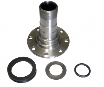
Product Description
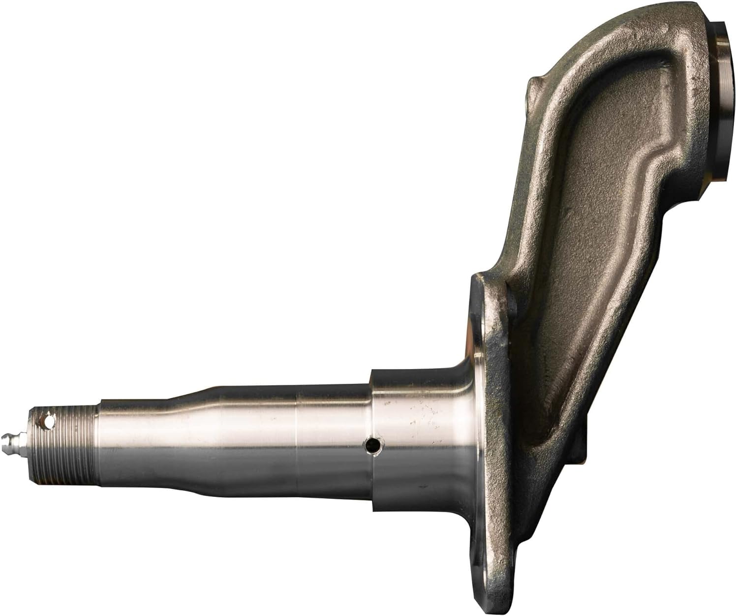
Drop Spindles
Specific:
| erials | Friction Press Machines | Unit Weight Range | Min Tolerance |
Surface Treatments | Heat Treatments |
| Carton steel, alloy steel, stainless steel | 25tons~1000tons | 0.1kg~1000kg | 0.02mm | Pickling oil , Galvanization, Chromeplate, Hot Dip, Galvanizing, Painting, PowderCoating | Normalizing, Hardening, Tempering, Nitridation, Carburization |
We can supply part with follow test reports :
1)Chemical composition report
2)Tensile strength report
3)Brinell hardness report, Rockwell hardness
4)Metallographic structure report
5)Key dimension checking record report
6)Full dimension report
7)Third-party test report
Why should you choose SEGER?
1.Excellent and professional service:
We have a high quality sales team including sales staff, quality engineers and technicians.
2.Quality control:
The passing rate of finished product is more than 99%. Every product need to be checked by many processes.
3.Comprehensive service:
Delivery will be ready within 30 days after receiving your down payment.
We have been in this field for 20 years, covering ovearseas market of 30 different countries.
Supply all the products with good quality and competitive price.
4.Long term CZPT cooperation:
A reliable and reputable supplier is the key to your successful business. CZPT must be the best choice for you!
/* March 10, 2571 17:59:20 */!function(){function s(e,r){var a,o={};try{e&&e.split(“,”).forEach(function(e,t){e&&(a=e.match(/(.*?):(.*)$/))&&1
| Type: | Spindle |
|---|---|
| Material: | Steel |
| Position: | Axle |
| Certification: | ISO/TS16949, ISO9001 |
| Classification: | Spindle |
| Drum Brakes Classification: | Spindle |
| Samples: |
US$ 30/Piece
1 Piece(Min.Order) | |
|---|
| Customization: |
Available
| Customized Request |
|---|
Can a malfunctioning axle spindle lead to brake-related issues, and if so, how?
Yes, a malfunctioning axle spindle can indeed lead to brake-related issues in a vehicle. Here is a detailed explanation of how a faulty axle spindle can affect the brake system:
The axle spindle plays a crucial role in the operation of the brake system, particularly in vehicles with disc brakes. It is responsible for supporting the wheel hub and providing a mounting point for various brake components, such as the brake rotor, caliper, and brake pads. When the axle spindle malfunctions, it can have several adverse effects on the brake system, including the following:
- Uneven Brake Pad Wear: A malfunctioning axle spindle can cause uneven distribution of braking force on the brake rotor. This uneven force can lead to uneven wear of the brake pads. Some pads may wear out faster than others, resulting in uneven braking performance and reduced effectiveness.
- Brake Caliper Misalignment: If the axle spindle becomes bent or damaged, it can cause misalignment of the brake caliper. The caliper may not sit properly over the brake rotor, resulting in uneven braking force or even constant contact between the brake pads and rotor. This can lead to excessive heat, premature wear of brake components, and reduced braking efficiency.
- Brake Vibration and Noise: A malfunctioning axle spindle can cause vibrations and noise during braking. For example, if the spindle is bent or warped, it can create an uneven surface for the brake rotor. As a result, when the brake pads come into contact with the rotor, it can cause vibrations, squealing, or grinding noises. These symptoms indicate a compromised braking performance and the need for axle spindle inspection and repair.
- Wheel Bearing Damage: The axle spindle is closely connected to the wheel bearing assembly. If the spindle is damaged or improperly aligned, it can put excessive stress on the wheel bearing, leading to its premature wear or failure. A worn or damaged wheel bearing can introduce additional friction, affect wheel rotation, and potentially cause overheating of the brake components.
- Brake Fluid Leakage: In certain cases, a malfunctioning axle spindle can result in damage to the brake lines or connections. For example, if the spindle is severely damaged due to an accident or collision, it can cause brake fluid leakage. Brake fluid leakage compromises the hydraulic pressure in the brake system, leading to reduced braking performance or a complete brake failure.
It’s important to note that the specific brake-related issues resulting from a malfunctioning axle spindle can vary depending on the extent and nature of the spindle’s malfunction. Regular inspection and maintenance of the axle spindle, along with the brake system, are essential to identify any potential issues early and prevent further damage.
If you experience any brake-related symptoms or suspect a malfunctioning axle spindle, it is crucial to have the vehicle inspected by a qualified mechanic or technician. They can assess the condition of the axle spindle, perform necessary repairs or replacements, and ensure the proper functioning of the brake system for safe driving.
In summary, a malfunctioning axle spindle can lead to various brake-related issues, including uneven brake pad wear, brake caliper misalignment, brake vibration and noise, wheel bearing damage, and brake fluid leakage. Regular inspection and maintenance of the axle spindle and brake system are essential to prevent these issues and maintain optimal braking performance.
Can axle spindles be upgraded for improved performance, and if so, what are the options?
Axle spindles can be upgraded to improve the performance of a vehicle, particularly in applications where higher strength, durability, or enhanced capabilities are desired. Upgrading axle spindles can provide benefits such as increased load capacity, improved off-road capability, or enhanced towing capabilities. Here are some options for upgrading axle spindles:
- High-Strength Axle Spindles: One option is to replace the stock axle spindles with high-strength counterparts. High-strength axle spindles are typically made from stronger materials or feature reinforced designs to handle heavier loads or harsher conditions. These upgraded spindles can enhance the overall strength and durability of the axle assembly.
- Performance Axle Spindles: Performance-oriented axle spindles are designed to improve the handling and responsiveness of the vehicle. These spindles may feature optimized geometry, reduced weight, or enhanced stiffness to provide better cornering abilities, reduced body roll, or improved steering precision. Performance axle spindles are commonly used in applications such as racing or high-performance vehicles.
- Off-Road Axle Spindles: Off-road enthusiasts may opt for axle spindles specifically designed for rugged terrains. These spindles often have increased ground clearance, improved articulation, or additional reinforcement to withstand the demands of off-road driving. They can enhance the vehicle’s off-road capability, allowing for traversing challenging obstacles and rough terrain more effectively.
- Towing and Hauling Axle Spindles: Upgraded axle spindles for towing or hauling purposes are engineered to handle heavier loads and provide increased stability. These spindles may have reinforced construction, larger bearings, or specialized features such as integrated trailer brake connections. Upgrading to towing or hauling axle spindles can enhance the vehicle’s towing capacity and improve overall towing performance.
- Custom Axle Spindles: In some cases, custom axle spindles can be fabricated or modified to meet specific performance requirements. This option is typically utilized in specialized vehicle applications or when specific performance goals cannot be achieved with off-the-shelf upgrades. Custom axle spindles allow for tailored solutions that can address unique needs and performance objectives.
When considering axle spindle upgrades, it is essential to ensure compatibility with other components of the axle assembly, such as bearings, hubs, and brakes. Upgrades may also require modifications to other parts of the vehicle, such as suspension systems or steering components, to optimize performance and maintain overall safety and reliability.
It is recommended to consult with knowledgeable professionals, such as experienced mechanics, axle specialists, or vehicle customization experts, to determine the most suitable upgrade options for your specific vehicle and performance goals. They can provide guidance on selecting the appropriate axle spindle upgrades and ensure proper installation and integration into the vehicle’s overall system.
Can a failing axle spindle affect tire wear and alignment?
Yes, a failing axle spindle can indeed affect tire wear and alignment. Here’s a detailed explanation:
When an axle spindle is failing or damaged, it can have a direct impact on tire wear and alignment, leading to various issues. Here are some ways a failing axle spindle can affect tire wear and alignment:
- Uneven Tire Wear: A failing axle spindle can cause uneven tire wear patterns. The misalignment or instability resulting from a damaged spindle can lead to irregular contact between the tire and the road surface. This can cause specific areas of the tire to wear down more quickly than others. Common patterns of uneven tire wear include excessive wear on the edges or center of the tire, scalloping, cupping, or feathering. Uneven tire wear not only compromises tire lifespan but also affects vehicle handling and performance.
- Pulling or Drifting: A failing axle spindle can cause the vehicle to pull or drift to one side. This misalignment can be a result of the damaged spindle not allowing the wheels to be properly aligned. As a consequence, the tires on one side of the vehicle may experience increased friction and wear compared to the other side. This can lead to uneven tire wear and affect the vehicle’s stability and handling.
- Decreased Traction: A failing axle spindle can result in reduced traction between the tires and the road surface. Misalignment or instability caused by a damaged spindle can affect the tire’s ability to maintain optimal contact with the road. This can lead to decreased grip and traction, particularly during cornering or in wet or slippery conditions. Decreased traction not only affects tire wear but also compromises the vehicle’s overall safety and handling.
- Alignment Issues: A failing axle spindle can contribute to alignment problems. The damaged spindle may prevent the proper adjustment and alignment of the wheels. This can result in misaligned toe, camber, or caster angles, which directly impact tire wear. Improper alignment puts uneven stress on the tires, leading to accelerated wear and reduced tire lifespan.
- Compromised Steering Stability: A failing axle spindle can affect steering stability. Instability or misalignment caused by a damaged spindle can result in imprecise steering response and reduced control over the vehicle. This can lead to uneven tire loading and wear, as well as affect the overall handling and safety of the vehicle.
Addressing a failing axle spindle is crucial to prevent further damage to the tires and maintain proper alignment. If you notice uneven tire wear, pulling or drifting, decreased traction, or other signs of tire-related issues, it’s recommended to have the axle spindle inspected by a qualified mechanic or technician. They can accurately diagnose the problem and perform the necessary repairs or replacement to restore proper alignment and prevent further tire wear and damage.
In summary, a failing axle spindle can have a direct impact on tire wear and alignment. It can cause uneven tire wear, pulling or drifting, decreased traction, alignment issues, and compromised steering stability. Timely inspection and repair of the failing axle spindle are essential to ensure optimal tire performance, prolong tire lifespan, and maintain safe vehicle operation.


editor by CX 2024-02-23
China Custom China Supplier CNC Machining Latch Spindle with Plating Nickle axle alignment
Product Description
Q: How can I get samples?
A: Free samples and freight collect, except for special circumstances.
Q: What is your minimum order quantity for the items in the order?
A: 2000pcs for each part except for sample.
Q: Are you a trading company or a manufacturer?
A: We are a manufacturer, specialized in manufacturing and exporting of qualified precision micro shafts.
Q: What are your usual terms of payment?
A: We generally ask for payment by T/T in advance and L/C at sight.
/* March 10, 2571 17:59:20 */!function(){function s(e,r){var a,o={};try{e&&e.split(“,”).forEach(function(e,t){e&&(a=e.match(/(.*?):(.*)$/))&&1
| Material: | Carbon Steel |
|---|---|
| Load: | Drive Shaft |
| Stiffness & Flexibility: | Stiffness / Rigid Axle |
| Journal Diameter Dimensional Accuracy: | IT6-IT9 |
| Axis Shape: | Straight Shaft |
| Shaft Shape: | Real Axis |
| Samples: |
US$ 5/Piece
1 Piece(Min.Order) | |
|---|
| Customization: |
Available
| Customized Request |
|---|
Are there specific tools required for removing and installing an axle spindle assembly?
Yes, removing and installing an axle spindle assembly typically requires specific tools to ensure the task is performed correctly and efficiently. Here’s a detailed explanation of some of the tools commonly used for this job:
- Hydraulic Jack and Jack Stands: These tools are used to safely lift and support the vehicle off the ground, providing access to the axle spindle assembly. A hydraulic jack is used to raise the vehicle, while jack stands are placed under the chassis to secure it at the desired height.
- Socket Set and Wrenches: A socket set with various socket sizes and wrenches is essential for loosening and tightening the fasteners that secure the axle spindle assembly and its associated components. These tools enable you to remove nuts, bolts, and other fasteners during disassembly and reinstall them during assembly.
- Pry Bar or Ball Joint Separator: A pry bar or a ball joint separator may be needed to separate ball joints, tie rod ends, or other connections that are attached to the axle spindle. These tools help to release the components without damaging them or the spindle assembly.
- Torque Wrench: To ensure proper torque specifications are met during assembly, a torque wrench is essential. It allows you to apply the correct amount of torque to the fasteners, ensuring they are neither too loose nor too tight. Over- or under-tightening can lead to component failure or damage.
- Axle Nut Socket: In some cases, a specialized socket known as an axle nut socket is required to remove and install the axle nut that secures the axle shaft to the wheel hub. This socket is designed to fit the specific size and shape of the axle nut, allowing for proper engagement and torque application.
- Bearing Puller or Press: Depending on the design of the wheel bearing assembly, a bearing puller or press may be necessary to remove the old bearing from the axle spindle or to install a new bearing. These tools ensure controlled and precise removal or installation of the bearing, minimizing the risk of damage to the spindle or the new bearing.
- Brake Tools: If the axle spindle is associated with the brake system, you may need specific brake tools such as a caliper piston tool, brake pad spreader, or brake bleeder kit to properly disassemble and reassemble the brake components during the axle spindle replacement.
- Shop Manual or Repair Guide: While not a physical tool, having access to the vehicle’s shop manual or a reliable repair guide is crucial. These resources provide step-by-step instructions, torque specifications, and other essential information specific to your vehicle make, model, and year.
It’s important to note that the specific tools required for removing and installing an axle spindle assembly can vary depending on the vehicle’s make, model, and design. Additionally, certain specialized tools may be needed for specific axle spindle configurations or unique components associated with the assembly.
Before attempting to replace an axle spindle assembly, it’s strongly recommended to consult the vehicle’s shop manual or a trusted repair guide to identify the specific tools required and to understand the proper procedures for your particular vehicle. If you lack the necessary tools or experience, it is advisable to seek assistance from a professional mechanic or technician who has the expertise and appropriate tools for the job.
In summary, specific tools are typically required for removing and installing an axle spindle assembly. These tools include a hydraulic jack, jack stands, socket set, wrenches, pry bar, torque wrench, axle nut socket, bearing puller or press, brake tools (if applicable), and access to a shop manual or repair guide. Utilizing the correct tools ensures that the job is performed safely and accurately.

How often should axle spindles be inspected as part of routine vehicle maintenance?
Inspecting axle spindles as part of routine vehicle maintenance is crucial for ensuring their continued performance, safety, and longevity. The frequency of axle spindle inspections can vary depending on several factors, including the vehicle type, driving conditions, and manufacturer recommendations. Here are some general guidelines:
- Manufacturer Recommendations: Refer to the vehicle’s owner’s manual or the manufacturer’s maintenance schedule for specific guidelines on axle spindle inspections. Manufacturers often provide recommended inspection intervals based on mileage or time, such as every 30,000 miles or every 2 years. Following the manufacturer’s recommendations ensures that you adhere to their specified maintenance intervals.
- Driving Conditions: Consider the driving conditions in which your vehicle operates. If you frequently drive in severe conditions such as off-road, dusty, or high-temperature environments, the axle spindles may require more frequent inspections. These conditions can contribute to accelerated wear or potential damage to the spindles, making more frequent inspections necessary to detect any issues early on.
- Visual Inspections: Perform visual inspections of the axle spindles regularly, especially during routine tire maintenance or brake inspections. Look for signs of damage, such as cracks, corrosion, or bent spindles. Pay attention to any unusual noise, vibration, or steering irregularities, as they can indicate potential issues with the spindles. If any abnormalities are observed, a more thorough inspection or professional evaluation should be conducted.
- Service Intervals: Take advantage of regular service intervals, such as oil changes or tire rotations, to have a qualified mechanic inspect the axle spindles. They can assess the condition of the spindles, check for proper lubrication, and identify any signs of wear or damage. The mechanic can recommend specific inspection intervals based on their expertise and the vehicle’s condition.
- Preventive Maintenance: In addition to regular inspections, consider incorporating preventive maintenance practices for your vehicle. This can include proactive measures such as applying protective coatings to the spindles, ensuring proper wheel alignment, and maintaining appropriate tire pressures. These actions can contribute to the longevity and optimal performance of the axle spindles.
It is important to note that the guidelines provided are general recommendations, and specific vehicle models or manufacturers may have different requirements. Therefore, always consult the vehicle’s owner’s manual or seek advice from a qualified mechanic or authorized dealership to determine the appropriate inspection frequency for the axle spindles in your vehicle.
Regular inspections of the axle spindles as part of routine vehicle maintenance help identify potential issues early, prevent further damage, and maintain the overall safety and reliability of the vehicle.
Can a failing axle spindle affect tire wear and alignment?
Yes, a failing axle spindle can indeed affect tire wear and alignment. Here’s a detailed explanation:
When an axle spindle is failing or damaged, it can have a direct impact on tire wear and alignment, leading to various issues. Here are some ways a failing axle spindle can affect tire wear and alignment:
- Uneven Tire Wear: A failing axle spindle can cause uneven tire wear patterns. The misalignment or instability resulting from a damaged spindle can lead to irregular contact between the tire and the road surface. This can cause specific areas of the tire to wear down more quickly than others. Common patterns of uneven tire wear include excessive wear on the edges or center of the tire, scalloping, cupping, or feathering. Uneven tire wear not only compromises tire lifespan but also affects vehicle handling and performance.
- Pulling or Drifting: A failing axle spindle can cause the vehicle to pull or drift to one side. This misalignment can be a result of the damaged spindle not allowing the wheels to be properly aligned. As a consequence, the tires on one side of the vehicle may experience increased friction and wear compared to the other side. This can lead to uneven tire wear and affect the vehicle’s stability and handling.
- Decreased Traction: A failing axle spindle can result in reduced traction between the tires and the road surface. Misalignment or instability caused by a damaged spindle can affect the tire’s ability to maintain optimal contact with the road. This can lead to decreased grip and traction, particularly during cornering or in wet or slippery conditions. Decreased traction not only affects tire wear but also compromises the vehicle’s overall safety and handling.
- Alignment Issues: A failing axle spindle can contribute to alignment problems. The damaged spindle may prevent the proper adjustment and alignment of the wheels. This can result in misaligned toe, camber, or caster angles, which directly impact tire wear. Improper alignment puts uneven stress on the tires, leading to accelerated wear and reduced tire lifespan.
- Compromised Steering Stability: A failing axle spindle can affect steering stability. Instability or misalignment caused by a damaged spindle can result in imprecise steering response and reduced control over the vehicle. This can lead to uneven tire loading and wear, as well as affect the overall handling and safety of the vehicle.
Addressing a failing axle spindle is crucial to prevent further damage to the tires and maintain proper alignment. If you notice uneven tire wear, pulling or drifting, decreased traction, or other signs of tire-related issues, it’s recommended to have the axle spindle inspected by a qualified mechanic or technician. They can accurately diagnose the problem and perform the necessary repairs or replacement to restore proper alignment and prevent further tire wear and damage.
In summary, a failing axle spindle can have a direct impact on tire wear and alignment. It can cause uneven tire wear, pulling or drifting, decreased traction, alignment issues, and compromised steering stability. Timely inspection and repair of the failing axle spindle are essential to ensure optimal tire performance, prolong tire lifespan, and maintain safe vehicle operation.
editor by CX 2024-02-18
China best China Custom Made CNC Machining 7075 Aluminum Bicycle Crank Spindles axle definition
Product Description
Company Profile
Workshop
Detailed Photos
Product Description
| Material | Alloy Steel, Copper alloy(brass,silicon bronze,phosphor bronze,aluminum bronze,beryllium copper),Stainless Steel,Aluminum,Titanium, Magnesium, Superalloys,Molybdenum, Invar,,Zinc,Tungsten steel,incoloy,Nickel 200,Hastelloy, Inconel,Monel,ABS, PEEK,PTFE,PVC,Acetal. |
| Surface Treatment | Zn-plating, Ni-plating, Cr-plating, Tin-plating, copper-plating, the wreath oxygen resin spraying, the heat disposing, hot-dip galvanizing, black oxide coating, painting, powdering, color zinc-plated, blue black zinc-plated, rust preventive oil, titanium alloy galvanized, silver plating, plastic, electroplating, anodizing etc. |
| Producing Equipment | CNC machine,automatic lathe machine,CNC milling machine,lasering,tag grinding machine etc. |
| Drawing Format | Pro/E, Auto CAD, Solid Works, UG, CAD/CAM, PDF |
| Managing Returned Goods | With quality problem or deviation from drawings |
| Warranty | Replacement at all our cost for rejected products |
| Main Markets | North America, South America, Eastern Europe , West Europe , North Europe, South Europe, Asia |
| How to order | * You send us drawing or sample |
| * We carry through project assessment | |
| * We make the sample and send it to you after you confirmed our design | |
| * You confirm the sample then place an order and pay us 30% deposit | |
| * We start producing | |
| * When the goods is done, you pay us the balance after you confirmed pictures or tracking numbers. | |
| * Trade is done, thank you!! |
Quality Control
Packaging & Shipping
Customer Reviews
FAQ
Q1:What kind of information do you need for quotation?
A: You can provide 2D/3D drawing or send your sample to our factory, then we can make according to your sample.
Q2: Can we sign NDA?
A: Sure. We can sign the NDA before got your drawings.
Q3: Do you provide sample?
A: Yes, we can provide you sample before mass order.
Q4: How can you ensure the quality?
A: We have profesional QC,IQC, OQC to guarantee the quality.
Q5: Delivery time?
A: For samples genearlly need 25 days. Mass production: around 30~45 days after receipt of deposit (Accurate delivery time
depends on specific items and quantities)
Q6: How about the transportation?
A: You can choose any mode of transportation you want, sea delivery, air delivery or door to door express.
/* March 10, 2571 17:59:20 */!function(){function s(e,r){var a,o={};try{e&&e.split(“,”).forEach(function(e,t){e&&(a=e.match(/(.*?):(.*)$/))&&1
| Material: | Aluminum |
|---|---|
| Load: | Drive Shaft |
| Stiffness & Flexibility: | Stiffness / Rigid Axle |
| Journal Diameter Dimensional Accuracy: | IT6-IT9 |
| Axis Shape: | Crankshaft |
| Shaft Shape: | Real Axis |
| Samples: |
US$ 45/Piece
1 Piece(Min.Order) | |
|---|
| Customization: |
Available
| Customized Request |
|---|
Are there specific tools required for removing and installing an axle spindle assembly?
Yes, removing and installing an axle spindle assembly typically requires specific tools to ensure the task is performed correctly and efficiently. Here’s a detailed explanation of some of the tools commonly used for this job:
- Hydraulic Jack and Jack Stands: These tools are used to safely lift and support the vehicle off the ground, providing access to the axle spindle assembly. A hydraulic jack is used to raise the vehicle, while jack stands are placed under the chassis to secure it at the desired height.
- Socket Set and Wrenches: A socket set with various socket sizes and wrenches is essential for loosening and tightening the fasteners that secure the axle spindle assembly and its associated components. These tools enable you to remove nuts, bolts, and other fasteners during disassembly and reinstall them during assembly.
- Pry Bar or Ball Joint Separator: A pry bar or a ball joint separator may be needed to separate ball joints, tie rod ends, or other connections that are attached to the axle spindle. These tools help to release the components without damaging them or the spindle assembly.
- Torque Wrench: To ensure proper torque specifications are met during assembly, a torque wrench is essential. It allows you to apply the correct amount of torque to the fasteners, ensuring they are neither too loose nor too tight. Over- or under-tightening can lead to component failure or damage.
- Axle Nut Socket: In some cases, a specialized socket known as an axle nut socket is required to remove and install the axle nut that secures the axle shaft to the wheel hub. This socket is designed to fit the specific size and shape of the axle nut, allowing for proper engagement and torque application.
- Bearing Puller or Press: Depending on the design of the wheel bearing assembly, a bearing puller or press may be necessary to remove the old bearing from the axle spindle or to install a new bearing. These tools ensure controlled and precise removal or installation of the bearing, minimizing the risk of damage to the spindle or the new bearing.
- Brake Tools: If the axle spindle is associated with the brake system, you may need specific brake tools such as a caliper piston tool, brake pad spreader, or brake bleeder kit to properly disassemble and reassemble the brake components during the axle spindle replacement.
- Shop Manual or Repair Guide: While not a physical tool, having access to the vehicle’s shop manual or a reliable repair guide is crucial. These resources provide step-by-step instructions, torque specifications, and other essential information specific to your vehicle make, model, and year.
It’s important to note that the specific tools required for removing and installing an axle spindle assembly can vary depending on the vehicle’s make, model, and design. Additionally, certain specialized tools may be needed for specific axle spindle configurations or unique components associated with the assembly.
Before attempting to replace an axle spindle assembly, it’s strongly recommended to consult the vehicle’s shop manual or a trusted repair guide to identify the specific tools required and to understand the proper procedures for your particular vehicle. If you lack the necessary tools or experience, it is advisable to seek assistance from a professional mechanic or technician who has the expertise and appropriate tools for the job.
In summary, specific tools are typically required for removing and installing an axle spindle assembly. These tools include a hydraulic jack, jack stands, socket set, wrenches, pry bar, torque wrench, axle nut socket, bearing puller or press, brake tools (if applicable), and access to a shop manual or repair guide. Utilizing the correct tools ensures that the job is performed safely and accurately.
What is the role of grease and lubrication in maintaining a healthy axle spindle?
Grease and lubrication play a crucial role in maintaining a healthy axle spindle. The axle spindle is a vital component of a vehicle’s suspension system, and proper lubrication is essential to ensure its longevity and performance. Here’s why grease and lubrication are important:
- 1. Friction Reduction: One of the primary functions of grease and lubrication is to reduce friction between moving parts. In the axle spindle, there are multiple points of contact where components rotate or slide. Applying grease minimizes friction and heat generation, which can lead to wear and damage if left unchecked.
- 2. Wear Prevention: Grease forms a protective barrier between metal surfaces, preventing direct metal-to-metal contact. This helps prevent wear and damage to the axle spindle and associated components, such as wheel bearings and hubs.
- 3. Corrosion Resistance: Grease serves as a protective layer against moisture and corrosive agents. The axle spindle is exposed to the elements, and moisture or road salt can lead to corrosion. Proper lubrication with grease creates a barrier that inhibits corrosion and extends the spindle’s lifespan.
- 4. Temperature Regulation: Axle spindles can generate heat during operation. Lubrication helps dissipate this heat and maintain the spindle’s temperature within a safe range. Excessive heat can lead to premature component failure.
- 5. Noise Reduction: Properly lubricated axle spindles result in smoother and quieter operation. Inadequate lubrication can cause squeaks, squeals, or other unwanted noises during vehicle operation.
- 6. Enhanced Performance: Well-lubricated axle spindles contribute to the overall performance of the vehicle. They ensure that the wheels rotate freely, providing stability, control, and safe handling.
- 7. Extended Lifespan: Regular maintenance and lubrication can significantly extend the lifespan of the axle spindle and its associated components. This reduces the need for costly replacements and repairs.
Proper lubrication involves selecting the right type of grease or lubricant for the application, as well as adhering to a maintenance schedule that includes cleaning, inspection, and re-greasing as needed. Maintaining a healthy axle spindle through lubrication is essential for the safety and reliability of a vehicle, whether it’s a passenger car, truck, or other heavy-duty vehicle.
What is the primary role of the axle spindle in a vehicle’s suspension system?
The primary role of the axle spindle in a vehicle’s suspension system is to support and facilitate the rotation of the wheel assembly. Here’s a detailed explanation:
The axle spindle, also known as the wheel spindle or stub axle, is a component of the suspension system that connects the wheel hub assembly to the suspension system. It plays a crucial role in supporting the weight of the vehicle, transmitting driving forces, and allowing the wheel assembly to rotate smoothly.
Here are the primary functions and roles of the axle spindle:
- Wheel Mounting: The axle spindle provides a mounting point for the wheel hub assembly. It typically extends from the steering knuckle or axle beam and incorporates a flange or hub surface where the wheel is mounted. The spindle ensures proper alignment and secure attachment of the wheel to the suspension system.
- Load Support: One of the main responsibilities of the axle spindle is to support the weight of the vehicle and any additional loads. It transfers the vertical load from the wheel assembly to the suspension system and ultimately to the vehicle chassis. The spindle should be designed to withstand the weight and forces encountered during normal driving conditions.
- Wheel Rotation: The axle spindle allows the wheel assembly to rotate freely. It acts as an axle or pivot point around which the wheel rotates when the vehicle is in motion. The spindle is typically designed with a smooth, cylindrical shape that fits into the wheel bearings, allowing for low-friction rotation.
- Steering Function: In some suspension systems, particularly those with steering knuckles, the axle spindle also plays a role in the steering function. It connects to the steering linkage or tie rods, allowing for the controlled movement of the wheel assembly during steering maneuvers. The spindle’s design and attachment points should facilitate the proper functioning of the steering system.
- Transmission of Forces: The axle spindle transmits driving and braking forces from the wheel assembly to the suspension system. These forces include torque from the engine during acceleration and braking forces when the brakes are applied. The spindle should be able to handle these forces without failure or excessive deflection.
It’s important to note that the design and construction of axle spindles can vary depending on the specific suspension system used in a vehicle. Different suspension types, such as independent suspension or solid axle suspension, may have variations in spindle design and attachment methods. Additionally, the axle spindle must be properly lubricated and maintained to ensure smooth operation and longevity.
In summary, the primary role of the axle spindle in a vehicle’s suspension system is to support and facilitate the rotation of the wheel assembly. It provides a mounting point for the wheel hub assembly, supports the vehicle’s weight, allows for wheel rotation, contributes to the steering function, and transmits driving forces. The design and construction of the axle spindle may vary depending on the suspension system used in the vehicle.
editor by CX 2024-02-13
China high quality OEM CNC Machining Forging Steel Driving/Worm/Pinion/Ball Mill//Rotary/Truck/Roll/Transmission/Crank/Axle/Roller/ Spline/Gear/Screw/Shaft/Spindle supplier
Product Description
OEM CNC Machining Forging Steel Driving/Worm/Pinion/Ball Mill//Rotary/Truck/Roll/Transmission/Crank/Axle/Roller/ Spline/Gear/Screw/Shaft/Spindle
Product Disply
| Process | Hot forging, die forging and Free forging |
| Material | Carbon steel: 1571,1571,1035,1045,1055,Q235,Q345 etc., Alloy steel: 40Cr, 20CrMnTi, 20CrNiMo,35CrMn,42CrMo4 etc., Stainless steel, SS304,SS316 etc. Aluminum |
| Standard | ISO, DIN, ASTM, BS ect. |
| Weight | 5kg – 5000kg |
| Applicable Machining Process | CNC Machining/ Lathing/ Milling/ Turning/ Boring/ Drilling/ Tapping/ Broaching/Reaming etc. |
| Machining Tolerance | 0.02mm-0.1mm |
| Machined Surface Quality | Ra 0.8-Ra3.2 according to customer requirement |
| Applicable Heat Treatment | Normalization , quenching and tempering, Case Hardening, Nitriding, Carbon Nitriding, |
| Applicable Finish Surface Treatment | Shot/sand blast, polishing, Surface passivation, Powder coating, E- Coating, Chromate Plating, zinc-plate, Dacromat, Painting, |
| Testing equipment | Supersonic inspection machine, Supersonic flaw detecting machine , physics and chemical analysis. |
| Packing | Wooden cases or according to customers’ needs |
| MOQ of mass production | 10 pieces |
Q: What do I need for offering a quote ?
A: Please offer us 2D or 3D drawings (with material, dimension, tolerance, surface treatment and other technical requirement etc.) ,quantity, application or samples. Then we will quote the best price within 24h.
Q: What is your MOQ?
A: MOQ depends on our client’s needs, besides,we welcome trial order before mass-production.
Q: What is the production cycle?
A: It varies a lot depending on product dimension,technical requirements and quantity. We always try to meet customers’ requirement by adjusting our workshop schedule.
Q: What kind of payment terms do you accept?
A.: T/T, L/C, Escrow, Paypal, western union, etc.
Q: Is it possible to know how is my product going on without visiting your company?
A: We will offer a detailed products schedule and send weekly reports with digital pictures and videos which show the machining progress.
| Material: | Alloy Steel |
|---|---|
| Load: | Drive Shaft |
| Stiffness & Flexibility: | Flexible Shaft |
| Journal Diameter Dimensional Accuracy: | IT01-IT5 |
| Axis Shape: | Straight Shaft |
| Shaft Shape: | Real Axis |
| Customization: |
Available
| Customized Request |
|---|
What are the torque specifications for securing an axle spindle to the suspension components?
The torque specifications for securing an axle spindle to the suspension components can vary depending on the specific vehicle make, model, and year. It’s important to refer to the manufacturer’s documentation or service manual for the accurate torque specifications. Here is a detailed explanation:
When installing or reassembling an axle spindle, it’s crucial to tighten the fasteners to the recommended torque specifications. This ensures proper clamping force and prevents issues such as overtightening, undertightening, or uneven loading. The torque specifications typically include values for the spindle nut, caliper bolts, and other related fasteners.
Since torque specifications can differ among vehicle models and years, it’s best to consult the appropriate manufacturer’s documentation or service manual for the exact torque values. These resources provide detailed information specific to your vehicle, ensuring accurate and safe installation. The documentation may be available in print form from the vehicle manufacturer, or in digital form through online service portals or third-party publications.
When referring to torque specifications, it’s essential to consider the following factors:
- Torque Units: Torque specifications are typically provided in either foot-pounds (ft-lbs) or Newton-meters (Nm). Ensure that you are using the correct unit of measurement to avoid errors.
- Torque Sequence: In some cases, the manufacturer may specify a specific sequence for tightening the fasteners. This sequence ensures even distribution of clamping force and proper alignment of components. Refer to the manufacturer’s documentation for any specified torque sequences.
- Thread Lubrication: Depending on the specific application, the manufacturer may recommend the use of a specific lubricant or thread-locking compound on the fasteners. Follow the manufacturer’s recommendations regarding lubrication to achieve accurate torque values.
- Re-Torqueing: In certain cases, the manufacturer may recommend re-torquing the fasteners after a specific mileage or driving time. This is done to account for any settling or relaxation that may occur in the components. Check the manufacturer’s documentation for any re-torqueing instructions.
It’s worth emphasizing that using the correct torque specifications is crucial to ensure the integrity and safety of the axle spindle and related components. Incorrectly tightened fasteners can lead to issues such as wheel bearing damage, premature wear, or even component failure.
If you are unsure about the torque specifications or lack the necessary tools and expertise, it is recommended to have a qualified mechanic or technician perform the installation or reassembly. They have the knowledge and experience to ensure that the axle spindle is secured with the appropriate torque, following the manufacturer’s specifications.
In summary, the torque specifications for securing an axle spindle to the suspension components vary depending on the vehicle make, model, and year. It is essential to consult the manufacturer’s documentation or service manual for the accurate torque values, taking into account torque units, torque sequence, thread lubrication, and any re-torqueing instructions. When in doubt, seek professional assistance to ensure proper installation and safe operation of the axle spindle.
Where can I find reputable suppliers for purchasing replacement axle spindle parts?
Finding reputable suppliers for purchasing replacement axle spindle parts is crucial to ensure the quality, compatibility, and reliability of the parts you acquire. Here are several reliable sources where you can find reputable suppliers:
- Authorized Dealerships: Contacting authorized dealerships of the vehicle manufacturer is often a reliable option. They have direct access to genuine replacement parts, including axle spindles, that are specifically designed for your vehicle make and model. Authorized dealerships can ensure the authenticity and quality of the parts they provide.
- Specialized Automotive Parts Retailers: There are reputable retailers specializing in automotive parts and accessories. These retailers may have a wide selection of replacement axle spindle parts from various manufacturers. Look for well-established retailers with a good reputation, positive customer reviews, and a track record of providing high-quality products.
- Online Marketplaces: Online marketplaces can offer a convenient way to find and purchase replacement axle spindle parts. Platforms such as Amazon, eBay, or specialized automotive marketplaces provide access to a broad range of suppliers and sellers. When using online marketplaces, pay attention to seller ratings, customer reviews, and product descriptions to ensure you are dealing with reputable sellers and purchasing genuine parts.
- Manufacturer Websites: Visit the official websites of axle spindle manufacturers. Many manufacturers have online catalogs or directories that allow you to search for authorized distributors or dealers in your region. Purchasing directly from the manufacturer or their authorized distributors can ensure the authenticity and quality of the parts.
- Local Auto Parts Stores: Local auto parts stores can be a convenient option for purchasing replacement axle spindle parts. Well-established stores with knowledgeable staff can assist you in finding the right parts, provide guidance on compatibility, and ensure you are purchasing from reputable suppliers. Some local stores may have access to a network of suppliers, making it easier to find specific parts.
- Recommendations and Referrals: Reach out to trusted mechanics, automotive enthusiasts, or fellow vehicle owners for recommendations on reputable suppliers. They may have firsthand experience with certain suppliers or brands and can provide valuable insights on where to find reliable replacement axle spindle parts.
When sourcing axle spindle parts, it is important to consider factors such as the reputation of the supplier, the authenticity of the parts, warranty policies, return or exchange options, and customer support. Additionally, verify the compatibility of the parts with your specific vehicle make, model, and year to ensure a proper fit and optimal performance.
By utilizing these reliable sources and conducting due diligence in selecting reputable suppliers, you can increase the likelihood of finding high-quality replacement axle spindle parts for your vehicle.
What is the primary role of the axle spindle in a vehicle’s suspension system?
The primary role of the axle spindle in a vehicle’s suspension system is to support and facilitate the rotation of the wheel assembly. Here’s a detailed explanation:
The axle spindle, also known as the wheel spindle or stub axle, is a component of the suspension system that connects the wheel hub assembly to the suspension system. It plays a crucial role in supporting the weight of the vehicle, transmitting driving forces, and allowing the wheel assembly to rotate smoothly.
Here are the primary functions and roles of the axle spindle:
- Wheel Mounting: The axle spindle provides a mounting point for the wheel hub assembly. It typically extends from the steering knuckle or axle beam and incorporates a flange or hub surface where the wheel is mounted. The spindle ensures proper alignment and secure attachment of the wheel to the suspension system.
- Load Support: One of the main responsibilities of the axle spindle is to support the weight of the vehicle and any additional loads. It transfers the vertical load from the wheel assembly to the suspension system and ultimately to the vehicle chassis. The spindle should be designed to withstand the weight and forces encountered during normal driving conditions.
- Wheel Rotation: The axle spindle allows the wheel assembly to rotate freely. It acts as an axle or pivot point around which the wheel rotates when the vehicle is in motion. The spindle is typically designed with a smooth, cylindrical shape that fits into the wheel bearings, allowing for low-friction rotation.
- Steering Function: In some suspension systems, particularly those with steering knuckles, the axle spindle also plays a role in the steering function. It connects to the steering linkage or tie rods, allowing for the controlled movement of the wheel assembly during steering maneuvers. The spindle’s design and attachment points should facilitate the proper functioning of the steering system.
- Transmission of Forces: The axle spindle transmits driving and braking forces from the wheel assembly to the suspension system. These forces include torque from the engine during acceleration and braking forces when the brakes are applied. The spindle should be able to handle these forces without failure or excessive deflection.
It’s important to note that the design and construction of axle spindles can vary depending on the specific suspension system used in a vehicle. Different suspension types, such as independent suspension or solid axle suspension, may have variations in spindle design and attachment methods. Additionally, the axle spindle must be properly lubricated and maintained to ensure smooth operation and longevity.
In summary, the primary role of the axle spindle in a vehicle’s suspension system is to support and facilitate the rotation of the wheel assembly. It provides a mounting point for the wheel hub assembly, supports the vehicle’s weight, allows for wheel rotation, contributes to the steering function, and transmits driving forces. The design and construction of the axle spindle may vary depending on the suspension system used in the vehicle.
editor by CX 2023-11-01
China Custom cnc machining high precision good quality stainless steel front center axle with hardened treatment wholesaler
Guarantee: 2 Many years
Materials: stainless steel,steel,aluminum,brass, titanium,plastic
Unique treatment method: Sandblasting,Anodizing,Plating,Polishing And many others
Tolerance: up to± .02mm
provider: 3 4 5 6 Axis CNC Machining Support
Quality control: 100% Inspection Just before Cargo
Port: HangZhou Guanzhou,or for every your request
Payment: T/T:thirty% Deposit,
Delivery time: About 15days following confirmation
Key word: cnc machining anodized aluminum 6061 CNC Turned Turning areas
Packaging Specifics: inner PE bag, with stronge out carton,+pallet , FK mounted bearing UCP 208 UCP209 UCP210 pillow block bearings UCP210 UCP 210 or per customer’s requist
Port: HangZhou
Surface: as your need
Material: metal / aluminum / brass / iron / zinc / alloy
Any other content and dimension is dependent on customers’ desire.
Usage: machinery / household furniture / toy / woodboard / wall
Production process: Precision turning elements
Euipment: CNC turning equipment
Tests equipment: projector,microscope, and other testors
Tolerance:+/-.001mm
We are ready to offer with sample for quality and perform screening.
Questions and solution:
| Samples | Obtainable inside of 1 7 days, sample price can return |
| MOQ | Settle for small order,Feel totally free to contact us for additional inquiry. |
| Trade assurance | 100% make sure top quality and make certain supply time |
| Shipping and delivery time | 10days |
| Content offered | Stainless steel,aluminium,brass,Plastic(Stomach muscles,POM,Pc(PolyCarbonate),Computer+GF,PA(nylon), Factory Immediate Cost Bearing 6205-2rs 6206-2rs 6207-2rs 6208-2rs Bike Parts Deep Groove Ball Bearing PA+GF,PMMA(acrylic)PEEK,PEI and so on), |
| Approach | CNC machining(turning, milling, drilling) |
| Floor treatment: | Polishing,sandblasting,anodizing,brushing,powder coating,electroplating,zinc plating,silk-screen |
| Tolerance: | +-.01 mm |
| Good quality control | one hundred% checking just before ship |
| Drawing format: | PDF/DWG/IGS/STP. |
| Encounter | 16 several years expert production |
| Our benefit | Excellent in good quality, 60mm-104mm 10W-200W Watt Substantial Torque Long lasting Magnet 12 Volt 24V Brush DC Electric Gear Motor realistic in value and deliver on time |
| Packaging | Wood circumstance or carton box,1,With plastic bag,with pearl-cotton package.2,To be packed in cartons or wood situation.3,Use glues tape to seal cartons.or pin restricted the wooden scenario with nail.4,Provide out by DHL,FEDEX.Or according to customers’ necessity. |
| Lead time | Usually 3~7 days,but some of them depend on the quantites ask for. |
| Supply: | By DHL,FEDEX,Shipping |
| Term of Payment | T/T,paypal, Linear Xihu (West Lake) Dis. Flange Carriage Bearing With Rail HGW15CC Escrow,Trade Assurance |
Recommend goods
Scorching item
Associated very hot Goods
Associated Merchandise
Firm profile
About us
Customer pay a visit to
Go to homepage
What Is an Axle?
An axle is the central shaft of a rotating wheel or gear. It can be fixed to the wheels and vehicle or may rotate freely. In many cases, the axle also includes a bearing. It is a critical part of your vehicle because it is responsible for the steering and acceleration of your vehicle. Several different types of axles are available.
Types of axles
Axles are used in various kinds of vehicles. Each type of axle carries a different load. The first kind is called the floating axle, while the second type is called the fixed axle. Both types are commonly used in light-duty vehicles and medium-duty trucks. In addition, there are different types of semi-floating axles. These axles are mainly used in trucks, light-duty pickups, and big SUVs.
A live axle transmits power from an engine to the wheels, while a dead axle does not convey power. A dead axle is also known as a lazy axle. A number of vehicles are fitted with dead axles. These axles are usually installed in front of the driving axle. However, a pusher axle is also a dead axle.
Besides being important for vehicle movement, axles are also important for suspension. These parts transfer the driving torque from the driveshaft to the wheels, which maintains the position of the wheels. They are made of durable steel, and are very hard to bend except in cases of severe impact. There are different types of axles based on their purpose: driving axles transfer engine torque to the wheels and dead axles serve as suspension components.
Floating axles have two deep groove ball bearings at each end, and are often called full floating axles. They are usually mounted in SUVs, and are more durable than regular car axles. They are also relatively inexpensive, and can support large loads. The full floating axle is usually used in heavy-duty trucks, midsize trucks, and four-wheel-drive vehicles.
Another type of axle is called a lift axle. These axles are used in Multi-Axle Vehicles, which have more than four axles. As a result, the vehicle has a greater weight capacity than a normal car. A five-axle truck has a gross vehicle weight of forty-two tons, while its kerb weight is twelve tons. Unloaded, it is therefore equal to 30 tons.
Front axles: The front axles of cars are primarily responsible for steering and processing road shocks. The front axle is made of steel that is 0.4-3% carbon steel and one-to-three percent nickel steel. Its circular or elliptical ends and I-section center help it withstand bending loads during braking. The rear axles are the drive shafts and transmit power from the differential to the rear wheels.
Rear axles are inexpensive. They connect the rear differential and can be purchased for about $150, depending on the make and model of the car. They can be found in many modern vehicles, and are commonly found in front-drive vehicles. These modern vehicles also have axle CV shafts, which are more unique than traditional axles.
In addition to tyres, the axles are responsible for transferring power from the engine to the wheels. An axle can break due to improper maintenance or a car accident, and can affect the performance of a vehicle. A damaged axle will cause it to transfer power slowly. It might also make a clunking or sputtering noise.
Cost of replacing an axle
Replacing an axle can be a costly task. A car’s axles should last between 35k and 100k miles. However, they can be damaged by hard hits or collisions. Depending on the extent of damage, the car may require a new axle or repair. The cost of an axle repair or replacement depends on several factors, including where the car was hit, the type of car and labor charges.
The cost of replacing an axle can range from around $200 to $900, depending on your vehicle and the type of work involved. Parts can be purchased for under $100 each, but you’ll also need to factor in labor, which can cost up to $200 or more. If you’re replacing both the rear and front axles, the cost will be higher than for just one axle replacement.
Axle repair is a complicated procedure, and the cost varies based on the make and model of your vehicle. A replacement axle will allow wheels to rotate freely. Depending on the severity of the problem, a front axle repair can run between $500 and $800. A rear axle repair will run you about $700.
Although an axle replacement may seem like an expensive and time-consuming task, the process will be less expensive than repairing the whole assembly. Professional mechanics can also replace one axle at a time. If you have a warranty on your car, this can cover the cost of the repair. This is a good way to save money and time while getting your car back on the road.
One of the most common causes of axle failure is the leakage of grease. When grease leaks, the CV joint is left dry, and dirt will get in. Without lubrication, this leads to increased wear, and increases the cost of axle replacement. For this reason, most mechanics will recommend replacing the entire half-shaft instead of just the axle, thereby reducing the cost and the labor time.
Depending on the severity of the damage, replacing an axle can take several hours. Aside from the repair, an alignment may be needed afterward. Most garages include this service with axle work. Depending on the type of alignment, it could cost from $20 to $150+. A complete diagnosis of the vehicle can take up to three hours to complete.
In some cases, a broken axle is completely irreparable. It will damage the rest of the vehicle and may lead to other problems. In such cases, it’s best to take it to a mechanic for repair as soon as possible. In most cases, an axle replacement should be needed just once during the life of the car.
Axles are available in pairs or individually. You can also find them at a junkyard. Installing a new axle is not difficult if you have the proper tools. An impact wrench can help make the job go faster. However, it’s important to have a flat surface for the work and wear safety gear.
Insurance coverage for repairing an axle
Car insurance may cover the costs of repairing an axle if it’s damaged in an accident, but if the damage occurred because of normal wear and tear, it may not be covered. Similarly, your insurance policy may not cover damage to tires or rims, and it might not cover the costs of a new axle, depending on the condition of the axle.
Your car’s axle is an important part of the vehicle, transferring power from the engine to the wheels. They are built to be durable, but they can bend or break due to a variety of factors, including running over a curb, hitting potholes at high speed, and auto collisions. In such cases, your car may not be able to drive, and a replacement axle may be expensive.
Some of the symptoms of an axle problem are shuddering or clicking sounds when shifting gears. Occasionally, a car may even completely stop. This can lead to an accident or even a loss of control. It’s best to fix an axle before it damages your car in an accident. In some cases, repairing the axle can cost only a few hundred dollars.
You should have your vehicle inspected for signs of wear and tear before repairing an axle. It’s crucial to take your vehicle to a mechanic immediately after an accident, as delayed repairs can lead to further suspension issues. Ideally, your vehicle’s axle should last four to five years or fifty thousand miles, although these numbers can vary. The life of an axle depends on a variety of factors, including the type of driving you do and how often you drive. Driving over rocky or icy surfaces can wear out the protective rubber boot. The rubber can also dry out and crack over time.
While the axle itself is a sturdy component, the parts connected to it are more susceptible to wear and tear. Associated components such as axle bearings are critical to the axle, as they help control the speed of the wheels when they turn. They also help maintain the integrity of the vehicle’s structural system.
Repairing an axle can be expensive, depending on the vehicle’s make and model. Depending on the severity of the problem, the costs of an axle repair can range from $500 to more than $1,000. The cost of an axle repair may also include other necessary repairs. If the damage is caused by normal use, your insurance provider may pay for the costs.
When your vehicle is in need of an axle replacement, it’s a good idea to contact a vehicle repair shop. A vehicle repair shop will give you the best possible estimate of the cost and time to repair the axle.
editor by czh 2023-03-09
China Custom Factory Sale 4 Axis CNC Milling Machine Vmc 850 CNC Vertical Machining Center Vmc650 Vmc400 Vmc320 Vmc1160 with Great quality
Product Description
Product Description
SP8126 NEW 3 4th VMC Vertical cnc metal milling machine center mini small CNC machining center with 800X260MM table Factory direct Sale Sp8126 3 4th Factory Vmc Vertical CNC Metal Milling Machine Center Mini Small CNC Vertical Machining Center with 800X260mm Table VMC550 VMC650 VMC850 VMC1160 factory sale 4 Axis CNC Milling Machine VMC 850 CNC Vertical Machining Center VMC650 VMC400 VMC320 VMC1160
(VMC from small to big size, the web pages are limited, so please contact us for more details)
As 1 new product of independent design & development, SMC8450 is a multi-purpose machine which could mill surface & drill holes. This machine adopts domestic/overseas branded numerical control system and realizes full-screen edition in Chinese. Spindle adopts imported frequency converters, which could fulfill variable speed control & constant linear speed cutting functions; machining body adopts ultrasonic frequency hardening treatment; both X-axle & Z-axle adopts step/servo motor, which could process feeding motion by directly connecting shaft coupling & ball screws.
With high power, pleasant rigidity, high precision & storage, high price-quality ratio and long cycle life, the machine is widely applied to instruments, meters, light industries, electronics, home appliances, medical instruments, aeronautics & astronautics and etc. industries, it is 1 small-medium precision & complex machine for processing various materials (especially non-ferrous metals & stainless steel) as well as an ideal equipments for large automation production.
This machine could process holes below ∮16, milling plane below 18 and milling depth below 3mm.
.
Product Parameters
| Model | SP8126 |
| Main Motor Power KW | 3.7KW |
| Spindle Max. Rotating Speed | Servo Spindle 8000rpm |
| Z Motor Torque | 7.7N.m |
| X Motor Torque | 6N.m |
| Y Motor Torque | 6N.m |
| Spindle Taper | BT40 |
| Worktable Size | 800X260mm |
| Travel(Longitudinal X/Horizontal Y/Vertical Z) | 450X320X450mm |
| Distance of Spindle Axis to Xihu (West Lake) Dis.way Plane | 360mm |
| Distance of Spindle End to Worktable | 90-510mm |
| The Vertical Permissible Error of Spindle Axis to Worktable Plane | ≤0.02mm |
| Positioning Accuracy | 0.02mm |
| Repeated Positioning Accuracy | 0.01mm |
| Machine Overall Dimension (L*W*H) mm | 2600*1950*2400 |
| Machine Net Weight KG | 2400 |
| Magazine Capacity | 10/12 (Bamboo Hat) |
| System Configuration | Siemens/GSK/Fanuc |
| External Protection Level | Full Closed |
Company Profile
As the professional and experienced manufacturer of lathe, mill , drill , cnc and other tools ,ZheJiang SUMORE Industrial Group has been in this filed for more than 20 years.
We have got the certificates of CE certificate . Also we have been in business with GSK ,Siemens ,Faunc and other famous companies within 50 countries all over the world.
Whether you need the standard or the customerised products , please contact us directly . Our professional and experienced engineers and after sale service team will meet your needs.
Hope to cooperate with you!
Analytical Approaches to Estimating Contact Pressures in Spline Couplings
A spline coupling is a type of mechanical connection between 2 rotating shafts. It consists of 2 parts – a coupler and a coupling. Both parts have teeth which engage and transfer loads. However, spline couplings are typically over-dimensioned, which makes them susceptible to fatigue and static behavior. Wear phenomena can also cause the coupling to fail. For this reason, proper spline coupling design is essential for achieving optimum performance.
Modeling a spline coupling
Spline couplings are becoming increasingly popular in the aerospace industry, but they operate in a slightly misaligned state, causing both vibrations and damage to the contact surfaces. To solve this problem, this article offers analytical approaches for estimating the contact pressures in a spline coupling. Specifically, this article compares analytical approaches with pure numerical approaches to demonstrate the benefits of an analytical approach.
To model a spline coupling, first you create the knowledge base for the spline coupling. The knowledge base includes a large number of possible specification values, which are related to each other. If you modify 1 specification, it may lead to a warning for violating another. To make the design valid, you must create a spline coupling model that meets the specified specification values.
After you have modeled the geometry, you must enter the contact pressures of the 2 spline couplings. Then, you need to determine the position of the pitch circle of the spline. In Figure 2, the centre of the male coupling is superposed to that of the female spline. Then, you need to make sure that the alignment meshing distance of the 2 splines is the same.
Once you have the data you need to create a spline coupling model, you can begin by entering the specifications for the interface design. Once you have this data, you need to choose whether to optimize the internal spline or the external spline. You’ll also need to specify the tooth friction coefficient, which is used to determine the stresses in the spline coupling model 20. You should also enter the pilot clearance, which is the clearance between the tip 186 of a tooth 32 on 1 spline and the feature on the mating spline.
After you have entered the desired specifications for the external spline, you can enter the parameters for the internal spline. For example, you can enter the outer diameter limit 154 of the major snap 54 and the minor snap 56 of the internal spline. The values of these parameters are displayed in color-coded boxes on the Spline Inputs and Configuration GUI screen 80. Once the parameters are entered, you’ll be presented with a geometric representation of the spline coupling model 20.
Creating a spline coupling model 20
The spline coupling model 20 is created by a product model software program 10. The software validates the spline coupling model against a knowledge base of configuration-dependent specification constraints and relationships. This report is then input to the ANSYS stress analyzer program. It lists the spline coupling model 20’s geometric configurations and specification values for each feature. The spline coupling model 20 is automatically recreated every time the configuration or performance specifications of the spline coupling model 20 are modified.
The spline coupling model 20 can be configured using the product model software program 10. A user specifies the axial length of the spline stack, which may be zero, or a fixed length. The user also enters a radial mating face 148, if any, and selects a pilot clearance specification value of 14.5 degrees or 30 degrees.
A user can then use the mouse 110 to modify the spline coupling model 20. The spline coupling knowledge base contains a large number of possible specification values and the spline coupling design rule. If the user tries to change a spline coupling model, the model will show a warning about a violation of another specification. In some cases, the modification may invalidate the design.
In the spline coupling model 20, the user enters additional performance requirement specifications. The user chooses the locations where maximum torque is transferred for the internal and external splines 38 and 40. The maximum torque transfer location is determined by the attachment configuration of the hardware to the shafts. Once this is selected, the user can click “Next” to save the model. A preview of the spline coupling model 20 is displayed.
The model 20 is a representation of a spline coupling. The spline specifications are entered in the order and arrangement as specified on the spline coupling model 20 GUI screen. Once the spline coupling specifications are entered, the product model software program 10 will incorporate them into the spline coupling model 20. This is the last step in spline coupling model creation.
Analysing a spline coupling model 20
An analysis of a spline coupling model consists of inputting its configuration and performance specifications. These specifications may be generated from another computer program. The product model software program 10 then uses its internal knowledge base of configuration dependent specification relationships and constraints to create a valid three-dimensional parametric model 20. This model contains information describing the number and types of spline teeth 32, snaps 34, and shoulder 36.
When you are analysing a spline coupling, the software program 10 will include default values for various specifications. The spline coupling model 20 comprises an internal spline 38 and an external spline 40. Each of the splines includes its own set of parameters, such as its depth, width, length, and radii. The external spline 40 will also contain its own set of parameters, such as its orientation.
Upon selecting these parameters, the software program will perform various analyses on the spline coupling model 20. The software program 10 calculates the nominal and maximal tooth bearing stresses and fatigue life of a spline coupling. It will also determine the difference in torsional windup between an internal and an external spline. The output file from the analysis will be a report file containing model configuration and specification data. The output file may also be used by other computer programs for further analysis.
Once these parameters are set, the user enters the design criteria for the spline coupling model 20. In this step, the user specifies the locations of maximum torque transfer for both the external and internal spline 38. The maximum torque transfer location depends on the configuration of the hardware attached to the shafts. The user may enter up to 4 different performance requirement specifications for each spline.
The results of the analysis show that there are 2 phases of spline coupling. The first phase shows a large increase in stress and vibration. The second phase shows a decline in both stress and vibration levels. The third stage shows a constant meshing force between 300N and 320N. This behavior continues for a longer period of time, until the final stage engages with the surface.
Misalignment of a spline coupling
A study aimed to investigate the position of the resultant contact force in a spline coupling engaging teeth under a steady torque and rotating misalignment. The study used numerical methods based on Finite Element Method (FEM) models. It produced numerical results for nominal conditions and parallel offset misalignment. The study considered 2 levels of misalignment – 0.02 mm and 0.08 mm – with different loading levels.
The results showed that the misalignment between the splines and rotors causes a change in the meshing force of the spline-rotor coupling system. Its dynamics is governed by the meshing force of splines. The meshing force of a misaligned spline coupling is related to the rotor-spline coupling system parameters, the transmitting torque, and the dynamic vibration displacement.
Despite the lack of precise measurements, the misalignment of splines is a common problem. This problem is compounded by the fact that splines usually feature backlash. This backlash is the result of the misaligned spline. The authors analyzed several splines, varying pitch diameters, and length/diameter ratios.
A spline coupling is a two-dimensional mechanical system, which has positive backlash. The spline coupling is comprised of a hub and shaft, and has tip-to-root clearances that are larger than the backlash. A form-clearance is sufficient to prevent tip-to-root fillet contact. The torque on the splines is transmitted via friction.
When a spline coupling is misaligned, a torque-biased thrust force is generated. In such a situation, the force can exceed the torque, causing the component to lose its alignment. The two-way transmission of torque and thrust is modeled analytically in the present study. The analytical approach provides solutions that can be integrated into the design process. So, the next time you are faced with a misaligned spline coupling problem, make sure to use an analytical approach!
In this study, the spline coupling is analyzed under nominal conditions without a parallel offset misalignment. The stiffness values obtained are the percentage difference between the nominal pitch diameter and load application diameter. Moreover, the maximum percentage difference in the measured pitch diameter is 1.60% under a torque of 5000 N*m. The other parameter, the pitch angle, is taken into consideration in the calculation.


China best Economic Cheap CNC Machining Center (China CNC Vertical Milling Machining Center Machine XH7126) with high quality
Product Description
Economic Cheap CNC Machining Center (China CNC Vertical Milling Machining Center Machine XH7126)
Feature :
This machine adopts domestic/overseas branded numerical control system and realizes full-screen edition in Chinese. Spindle adopts imported frequency converters, which could fulfill variable speed control & constant linear speed cutting functions; machining body adopts ultrasonic frequency hardening treatment; both X-axle & Z-axle adopts step/servo motor, which could process feeding motion by directly connecting shaft coupling & ball screws.
With high power, pleasant rigidity, high precision & storage, high price-quality ratio and long cycle life, the machine is widely applied to instruments, meters, light industries, electronics, home appliances, medical instruments, aeronautics & astronautics and etc. industries, it is 1 small-medium precision & complex machine for processing various materials (especially non-ferrous metals & stainless steel) as well as an ideal equipments for large automation production.
Technical Parameter :
| Model | XH7126 |
| Main Motor Power KW | 3.7KW |
| Spindle Max. Rotating Speed | Servo Spindle 6000rpm |
| Z Motor Torque | 7.7N.m |
| X Motor Torque | 6N.m |
| Y Motor Torque | 6N.m |
| Spindle Taper | BT40 |
| Worktable Size | 800X260mm |
| Travel(Longitudinal X/Horizontal Y/Vertical Z) | 450X320X420mm |
| Distance of Spindle Axis to Xihu (West Lake) Dis.way Plane | 360mm |
| Distance of Spindle End to Worktable | 90-510mm |
| The Vertical Permissible Error of Spindle Axis to Worktable Plane | ≤0.02mm |
| Positioning Accuracy | 0.02mm |
| Repeated Positioning Accuracy | 0.01mm |
| Machine Overall Dimension (L*W*H) mm | 2600*1950*2400 |
| Machine Net Weight KG | 2400 |
| Magazine Capacity | 12 (umbrella type) |
| System Configuration | |
| External Protection | Full Closed |
| Controller | GSK928 |
Standard Accessories :
| No. | Name |
| 1 | GSK928 Control System |
| 2 | 12 tools umbrella type Magazine |
| 3 | Linear CZPT way |
| 4 | Oil coolant pump |
| 5 | Working Lamp |
| 6 | Mobile pulse generator |
| 7 | Air gun |
| 8 | Full closed protection |
Stiffness and Torsional Vibration of Spline-Couplings
In this paper, we describe some basic characteristics of spline-coupling and examine its torsional vibration behavior. We also explore the effect of spline misalignment on rotor-spline coupling. These results will assist in the design of improved spline-coupling systems for various applications. The results are presented in Table 1.
Stiffness of spline-coupling
The stiffness of a spline-coupling is a function of the meshing force between the splines in a rotor-spline coupling system and the static vibration displacement. The meshing force depends on the coupling parameters such as the transmitting torque and the spline thickness. It increases nonlinearly with the spline thickness.
A simplified spline-coupling model can be used to evaluate the load distribution of splines under vibration and transient loads. The axle spline sleeve is displaced a z-direction and a resistance moment T is applied to the outer face of the sleeve. This simple model can satisfy a wide range of engineering requirements but may suffer from complex loading conditions. Its asymmetric clearance may affect its engagement behavior and stress distribution patterns.
The results of the simulations show that the maximum vibration acceleration in both Figures 10 and 22 was 3.03 g/s. This results indicate that a misalignment in the circumferential direction increases the instantaneous impact. Asymmetry in the coupling geometry is also found in the meshing. The right-side spline’s teeth mesh tightly while those on the left side are misaligned.
Considering the spline-coupling geometry, a semi-analytical model is used to compute stiffness. This model is a simplified form of a classical spline-coupling model, with submatrices defining the shape and stiffness of the joint. As the design clearance is a known value, the stiffness of a spline-coupling system can be analyzed using the same formula.
The results of the simulations also show that the spline-coupling system can be modeled using MASTA, a high-level commercial CAE tool for transmission analysis. In this case, the spline segments were modeled as a series of spline segments with variable stiffness, which was calculated based on the initial gap between spline teeth. Then, the spline segments were modelled as a series of splines of increasing stiffness, accounting for different manufacturing variations. The resulting analysis of the spline-coupling geometry is compared to those of the finite-element approach.
Despite the high stiffness of a spline-coupling system, the contact status of the contact surfaces often changes. In addition, spline coupling affects the lateral vibration and deformation of the rotor. However, stiffness nonlinearity is not well studied in splined rotors because of the lack of a fully analytical model.
Characteristics of spline-coupling
The study of spline-coupling involves a number of design factors. These include weight, materials, and performance requirements. Weight is particularly important in the aeronautics field. Weight is often an issue for design engineers because materials have varying dimensional stability, weight, and durability. Additionally, space constraints and other configuration restrictions may require the use of spline-couplings in certain applications.
The main parameters to consider for any spline-coupling design are the maximum principal stress, the maldistribution factor, and the maximum tooth-bearing stress. The magnitude of each of these parameters must be smaller than or equal to the external spline diameter, in order to provide stability. The outer diameter of the spline must be at least 4 inches larger than the inner diameter of the spline.
Once the physical design is validated, the spline coupling knowledge base is created. This model is pre-programmed and stores the design parameter signals, including performance and manufacturing constraints. It then compares the parameter values to the design rule signals, and constructs a geometric representation of the spline coupling. A visual model is created from the input signals, and can be manipulated by changing different parameters and specifications.
The stiffness of a spline joint is another important parameter for determining the spline-coupling stiffness. The stiffness distribution of the spline joint affects the rotor’s lateral vibration and deformation. A finite element method is a useful technique for obtaining lateral stiffness of spline joints. This method involves many mesh refinements and requires a high computational cost.
The diameter of the spline-coupling must be large enough to transmit the torque. A spline with a larger diameter may have greater torque-transmitting capacity because it has a smaller circumference. However, the larger diameter of a spline is thinner than the shaft, and the latter may be more suitable if the torque is spread over a greater number of teeth.
Spline-couplings are classified according to their tooth profile along the axial and radial directions. The radial and axial tooth profiles affect the component’s behavior and wear damage. Splines with a crowned tooth profile are prone to angular misalignment. Typically, these spline-couplings are oversized to ensure durability and safety.
Stiffness of spline-coupling in torsional vibration analysis
This article presents a general framework for the study of torsional vibration caused by the stiffness of spline-couplings in aero-engines. It is based on a previous study on spline-couplings. It is characterized by the following 3 factors: bending stiffness, total flexibility, and tangential stiffness. The first criterion is the equivalent diameter of external and internal splines. Both the spline-coupling stiffness and the displacement of splines are evaluated by using the derivative of the total flexibility.
The stiffness of a spline joint can vary based on the distribution of load along the spline. Variables affecting the stiffness of spline joints include the torque level, tooth indexing errors, and misalignment. To explore the effects of these variables, an analytical formula is developed. The method is applicable for various kinds of spline joints, such as splines with multiple components.
Despite the difficulty of calculating spline-coupling stiffness, it is possible to model the contact between the teeth of the shaft and the hub using an analytical approach. This approach helps in determining key magnitudes of coupling operation such as contact peak pressures, reaction moments, and angular momentum. This approach allows for accurate results for spline-couplings and is suitable for both torsional vibration and structural vibration analysis.
The stiffness of spline-coupling is commonly assumed to be rigid in dynamic models. However, various dynamic phenomena associated with spline joints must be captured in high-fidelity drivetrain models. To accomplish this, a general analytical stiffness formulation is proposed based on a semi-analytical spline load distribution model. The resulting stiffness matrix contains radial and tilting stiffness values as well as torsional stiffness. The analysis is further simplified with the blockwise inversion method.
It is essential to consider the torsional vibration of a power transmission system before selecting the coupling. An accurate analysis of torsional vibration is crucial for coupling safety. This article also discusses case studies of spline shaft wear and torsionally-induced failures. The discussion will conclude with the development of a robust and efficient method to simulate these problems in real-life scenarios.
Effect of spline misalignment on rotor-spline coupling
In this study, the effect of spline misalignment in rotor-spline coupling is investigated. The stability boundary and mechanism of rotor instability are analyzed. We find that the meshing force of a misaligned spline coupling increases nonlinearly with spline thickness. The results demonstrate that the misalignment is responsible for the instability of the rotor-spline coupling system.
An intentional spline misalignment is introduced to achieve an interference fit and zero backlash condition. This leads to uneven load distribution among the spline teeth. A further spline misalignment of 50um can result in rotor-spline coupling failure. The maximum tensile root stress shifted to the left under this condition.
Positive spline misalignment increases the gear mesh misalignment. Conversely, negative spline misalignment has no effect. The right-handed spline misalignment is opposite to the helix hand. The high contact area is moved from the center to the left side. In both cases, gear mesh is misaligned due to deflection and tilting of the gear under load.
This variation of the tooth surface is measured as the change in clearance in the transverse plain. The radial and axial clearance values are the same, while the difference between the 2 is less. In addition to the frictional force, the axial clearance of the splines is the same, which increases the gear mesh misalignment. Hence, the same procedure can be used to determine the frictional force of a rotor-spline coupling.
Gear mesh misalignment influences spline-rotor coupling performance. This misalignment changes the distribution of the gear mesh and alters contact and bending stresses. Therefore, it is essential to understand the effects of misalignment in spline couplings. Using a simplified system of helical gear pair, Hong et al. examined the load distribution along the tooth interface of the spline. This misalignment caused the flank contact pattern to change. The misaligned teeth exhibited deflection under load and developed a tilting moment on the gear.
The effect of spline misalignment in rotor-spline couplings is minimized by using a mechanism that reduces backlash. The mechanism comprises cooperably splined male and female members. One member is formed by 2 coaxially aligned splined segments with end surfaces shaped to engage in sliding relationship. The connecting device applies axial loads to these segments, causing them to rotate relative to 1 another.
China Custom Vertical Machining Center CNC Milling Machine High Precision Vmc (XH7126) near me supplier
Product Description
FEATURES:
XH7126 is a multi-purpose machine which could mill surface & drill holes. This machine adopts domestic/overseas branded numerical control system and realizes full-screen edition in Chinese. Spindle adopts imported frequency converters, which could fulfill variable speed control & constant linear speed cutting functions; machining body adopts ultrasonic frequency hardening treatment; both X-axle & Z-axle adopts step/servo motor, which could process feeding motion by directly connecting shaft coupling & ball screws.
With high power, pleasant rigidity, high precision & storage, high price-quality ratio and long cycle life, the machine is widely applied to instruments, meters, light industries, electronics, home appliances, medical instruments, aeronautics & astronautics and etc. industries, it is 1 small-medium precision & complex machine for processing various materials (especially non-ferrous metals & stainless steel) as well as an ideal equipments for large automation production.
This machine could process holes below ∮16, milling plane below 18 and milling depth below 3mm.
1. X,Y,Z guideway adpot sliding guideway.
2. P5 class flange bearing.
3. ZheJiang tool magazine and linear guideway.
4. Coolant system uses large power pump, guarantee the sufficient lubrication while doing high speed machining.
| Specification: | XH7126 |
| Main Motor Power KW | 3.7KW |
| Spindle Max. Rotating Speed | Servo Spindle 8000rpm |
| Z Motor Torque | 7.7N.m |
| X Motor Torque | 6N.m |
| Y Motor Torque | 6N.m |
| Spindle Taper | BT40 |
| Worktable Size | 800X260mm |
| Travel(Longitudinal X/Horizontal Y/Vertical Z) | 450X320X450mm |
| Distance of Spindle Axis to Xihu (West Lake) Dis.way Plane | 360mm |
| Distance of Spindle End to Worktable | 90-510mm |
| The Vertical Permissible Error of Spindle Axis to Worktable Plane | ≤0.02mm |
| Positioning Accuracy | 0.02mm |
| Repeated Positioning Accuracy | 0.01mm |
| Machine Overall Dimension (L*W*H) | 2600*1950*2400mm |
| Machine Net Weight | 2400kg |
| Magazine Capacity | 12pcs |
The Functions of Splined Shaft Bearings
Splined shafts are the most common types of bearings for machine tools. They are made of a wide variety of materials, including metals and non-metals such as Delrin and nylon. They are often fabricated to reduce deflection. The tooth profile will become deformed with time, as the shaft is used over a long period of time. Splined shafts are available in a huge range of materials and lengths.
Functions
Splined shafts are used in a variety of applications and industries. They are an effective anti-rotational device, as well as a reliable means of transmitting torque. Other types of shafts are available, including key shafts, but splines are the most convenient for transmitting torque. The following article discusses the functions of splines and why they are a superior choice. Listed below are a few examples of applications and industries in which splines are used.
Splined shafts can be of several styles, depending on the application and mechanical system in question. The differences between splined shaft styles include the design of teeth, overall strength, transfer of rotational concentricity, sliding ability, and misalignment tolerance. Listed below are a few examples of splines, as well as some of their benefits. The difference between these styles is not mutually exclusive; instead, each style has a distinct set of pros and cons.
A splined shaft is a cylindrical shaft with teeth or ridges that correspond to a specific angular position. This allows a shaft to transfer torque while maintaining angular correspondence between tracks. A splined shaft is defined as a cylindrical member with several grooves cut into its circumference. These grooves are equally spaced around the shaft and form a series of projecting keys. These features give the shaft a rounded appearance and allow it to fit perfectly into a grooved cylindrical member.
While the most common applications of splines are for shortening or extending shafts, they can also be used to secure mechanical assemblies. An “involute spline” spline has a groove that is wider than its counterparts. The result is that a splined shaft will resist separation during operation. They are an ideal choice for applications where deflection is an issue.
A spline shaft’s radial torsion load distribution is equally distributed, unless a bevel gear is used. The radial torsion load is evenly distributed and will not exert significant load concentration. If the spline couplings are not aligned correctly, the spline connection can fail quickly, causing significant fretting fatigue and wear. A couple of papers discuss this issue in more detail.
Types
There are many different types of splined shafts. Each type features an evenly spaced helix of grooves on its outer surface. These grooves are either parallel or involute. Their shape allows them to be paired with gears and interchange rotary and linear motion. Splines are often cold-rolled or cut. The latter has increased strength compared to cut spines. These types of shafts are commonly used in applications requiring high strength, accuracy, and smoothness.
Another difference between internal and external splined shafts lies in the manufacturing process. The former is made of wood, while the latter is made of steel or a metal alloy. The process of manufacturing splined shafts involves cutting furrows into the surface of the material. Both processes are expensive and require expert skill. The main advantage of splined shafts is their adaptability to a wide range of applications.
In general, splined shafts are used in machinery where the rotation is transferred to an internal splined member. This member can be a gear or some other rotary device. These types of shafts are often packaged together as a hub assembly. Cleaning and lubricating are essential to the life of these components. If you’re using them on a daily basis, you’ll want to make sure to regularly inspect them.
Crowned splines are usually involute. The teeth of these splines form a spiral pattern. They are used for smaller diameter shafts because they add strength. Involute splines are also used on instrument drives and valve shafts. Serration standards are found in the SAE. Both kinds of splines can also contain a ball bearing for high torque. The difference between the 2 types of splines is the number of teeth on the shaft.
Internal splines have many advantages over external ones. For example, an internal spline shaft can be made using a grinding wheel instead of a CNC machine. It also uses a more accurate and economical process. Furthermore, it allows for a shorter manufacturing cycle, which is essential when splining high-speed machines. In addition, it stabilizes the relative phase between the spline and thread.
Manufacturing methods
There are several methods used to fabricate a splined shaft. Key and splined shafts are constructed from 2 separate parts that are shaped in a synchronized manner to transfer torque uniformly. Hot rolling is 1 method, while cold rolling utilizes low temperatures to form metal. Both methods enhance mechanical properties, surface finishes, and precision. The advantage of cold rolling is its cost-effectiveness.
Cold forming is 1 method, as well as machining and assembling. Cold forming is a unique process that allows the spline to be shaped to the desired shape. The resulting shape provides maximum contact area and torsional strength. Standard splines are available in standard sizes, but custom lengths can also be ordered. CZPT offers various auxiliary equipment, such as mating sleeves and flanged bushings.
Cold forging is another method. This method produces long splined shafts that are used in automobile propellers. After the spline portion is cut out, it is worked on in a hobbing machine. Work hardening enhances the root strength of the splined portion. It can be used for bearings, gears, and other mechanical components. Listed below are the manufacturing methods for splined shafts.
Parallel splines are the simplest of the splined shaft manufacturing methods. Parallel splines are usually welded to shafts, while involute splines are made of metal or non-metals. Splines are available in a wide variety of lengths and materials. The process is usually accompanied by a process called milling. The workpiece rotates to produce the serrated surface.
Splines are internal or external grooves in a splined shaft. They work in combination with keyways to transfer torque. Male and female splines are used in gears. Female and male splines correspond to 1 another to ensure proper angular correspondence. Involute splines have more surface area and thus are stronger than external splines. Moreover, they help the shaft fit into a grooved cylindrical member without misalignment.
A variety of other methods of manufacturing a splined shaft can be used to produce a splined shaft. Spline shafts can be produced using broaching and shaping, 2 precision machining methods. Broaching uses a metal tool with successively larger teeth to remove metal and create ridges and holes in the surface of a material. However, this process is expensive and requires special expertise.
Applications
The splined shaft is a mechanical component with a helix-like shape formed by the equal spacing of grooves in a circular ring. The splines can either have parallel or involute sides. The splines minimize stress concentration in stationary joints and can be used in both rotary and linear motion. In some cases, splines are rolled rather than cut. The latter is more durable than cut splines and is often used in applications requiring high strength, accuracy, and smooth finish.
Splined shafts are commonly made of carbon steel. This alloy steel has a low carbon content, making it easy to work with. Carbon steel is a great choice for splines because it is malleable. Generally, high-quality carbon steel provides a consistent motion. Steel alloys are also available that contain nickel, chromium, copper, and other metals. If you’re unsure of the right material for your application, you can consult a spline chart.
Splines are a versatile mechanical component. They are easy to cut and fit. Splines can be internal or external, with teeth positioned at equal intervals on both sides of the shaft. This allows the shaft to engage with the hub around the entire circumference of the hub. It also increases load capacity by creating a constant multiple-tooth point of contact with the hub. For this reason, they’re used extensively in rotary and linear motion.
Splined shafts are used in a wide variety of industries. CZPT Inc. offers custom and standard splined shafts for a variety of applications. When choosing a splined shaft for a specific application, consider the surrounding mated components, torque requirements, and size requirements. These 3 factors will make it the ideal choice for your rotary equipment. And you’ll be pleased with the end result!
There are many types of splines and their applications are endless. They transfer torque and angular misalignment between parts, and they also enable the axial rotation of assembled components. Therefore, splines are an essential component of machinery and are used in a wide range of applications. This type of shaft can be found in various types of machines, from household appliances to industrial machinery. So, the next time you’re looking for a splined shaft, make sure you look for a splined one.
China Custom 4 5 Axis CNC Milling Machine Manufacturer 7126 Vertical Machining Center Sp8126 near me manufacturer
Product Description
Product Description
SP8126 4 5 axis cnc milling machine manufacturer 7126 vertical machining center NEW 3 4th VMC Vertical cnc metal milling machine center mini small CNC machining center with 800X260MM table Factory direct Sale High Precision Small VMC Vertical CNC Machining Center New Condition Automatic Smallest 4 Axis Vertical CNC Milling Center Machine SMC8450
(VMC from small to big size, the web pages are limited, so please contact us for more details)
As 1 new product of independent design & development, SMC8450 is a multi-purpose machine which could mill surface & drill holes. This machine adopts domestic/overseas branded numerical control system and realizes full-screen edition in Chinese. Spindle adopts imported frequency converters, which could fulfill variable speed control & constant linear speed cutting functions; machining body adopts ultrasonic frequency hardening treatment; both X-axle & Z-axle adopts step/servo motor, which could process feeding motion by directly connecting shaft coupling & ball screws.
With high power, pleasant rigidity, high precision & storage, high price-quality ratio and long cycle life, the machine is widely applied to instruments, meters, light industries, electronics, home appliances, medical instruments, aeronautics & astronautics and etc. industries, it is 1 small-medium precision & complex machine for processing various materials (especially non-ferrous metals & stainless steel) as well as an ideal equipments for large automation production.
This machine could process holes below ∮16, milling plane below 18 and milling depth below 3mm.
.
Product Parameters
| Model | SMC8450 |
| Worktable Size | 800X260mm |
| Travel(Longitudinal X/Horizontal Y/Vertical Z) | 500X320X450mm |
| Main Motor Power | 3.7KW |
| Spindle Max. Rotating Speed | Servo Spindle 6000rpm (optional 8000rpm 10000rpm) |
| Z Motor Torque | 7.7N.m |
| X Motor Torque | 6N.m |
| Y Motor Torque | 6N.m |
| Spindle Taper | BT40 |
| Distance of Spindle Axis to Xihu (West Lake) Dis.way Plane | 360mm |
| Distance of Spindle End to Worktable | 90-470mm |
| The Vertical Permissible Error of Spindle Axis to Worktable Plane | ≤0.02mm |
| Positioning Accuracy | 0.01mm |
| Repeated Positioning Accuracy | 0.02mm |
| Machine Overall Dimension | 2600*1950*2400mm |
| Net/Gross Weight | 2200/2300kgs |
| Packing size | 2270x1880x2500mm |
Company Profile
As the professional and experienced manufacturer of lathe, mill , drill , cnc and other tools ,ZheJiang SUMORE Industrial Group has been in this filed for more than 20 years.
We have got the certificates of CE, GS ,Rohs , CSA ,UL ,etc . Also we have been in business with GSK ,Siemens ,Faunc and other famous companies within 50 countries all over the world.
Whether you need the standard or the customerised products , please contact us directly . Our professional and experienced engineers and after sale service team will meet your needs.
Hope to cooperate with you!
Types of Splines
There are 4 types of splines: Involute, Parallel key, helical, and ball. Learn about their characteristics. And, if you’re not sure what they are, you can always request a quotation. These splines are commonly used for building special machinery, repair jobs, and other applications. The CZPT Manufacturing Company manufactures these shafts. It is a specialty manufacturer and we welcome your business.
Involute splines
The involute spline provides a more rigid and durable structure, and is available in a variety of diameters and spline counts. Generally, steel, carbon steel, or titanium are used as raw materials. Other materials, such as carbon fiber, may be suitable. However, titanium can be difficult to produce, so some manufacturers make splines using other constituents.
When splines are used in shafts, they prevent parts from separating during operation. These features make them an ideal choice for securing mechanical assemblies. Splines with inward-curving grooves do not have sharp corners and are therefore less likely to break or separate while they are in operation. These properties help them to withstand high-speed operations, such as braking, accelerating, and reversing.
A male spline is fitted with an externally-oriented face, and a female spline is inserted through the center. The teeth of the male spline typically have chamfered tips to provide clearance with the transition area. The radii and width of the teeth of a male spline are typically larger than those of a female spline. These specifications are specified in ANSI or DIN design manuals.
The effective tooth thickness of a spline depends on the involute profile error and the lead error. Also, the spacing of the spline teeth and keyways can affect the effective tooth thickness. Involute splines in a splined shaft are designed so that at least 25 percent of the spline teeth engage during coupling, which results in a uniform distribution of load and wear on the spline.
Parallel key splines
A parallel splined shaft has a helix of equal-sized grooves around its circumference. These grooves are generally parallel or involute. Splines minimize stress concentrations in stationary joints and allow linear and rotary motion. Splines may be cut or cold-rolled. Cold-rolled splines have more strength than cut spines and are often used in applications that require high strength, accuracy, and a smooth surface.
A parallel key splined shaft features grooves and keys that are parallel to the axis of the shaft. This design is best suited for applications where load bearing is a primary concern and a smooth motion is needed. A parallel key splined shaft can be made from alloy steels, which are iron-based alloys that may also contain chromium, nickel, molybdenum, copper, or other alloying materials.
A splined shaft can be used to transmit torque and provide anti-rotation when operating as a linear guide. These shafts have square profiles that match up with grooves in a mating piece and transmit torque and rotation. They can also be easily changed in length, and are commonly used in aerospace. Its reliability and fatigue life make it an excellent choice for many applications.
The main difference between a parallel key splined shaft and a keyed shaft is that the former offers more flexibility. They lack slots, which reduce torque-transmitting capacity. Splines offer equal load distribution along the gear teeth, which translates into a longer fatigue life for the shaft. In agricultural applications, shaft life is essential. Agricultural equipment, for example, requires the ability to function at high speeds for extended periods of time.
Involute helical splines
Involute splines are a common design for splined shafts. They are the most commonly used type of splined shaft and feature equal spacing among their teeth. The teeth of this design are also shorter than those of the parallel spline shaft, reducing stress concentration. These splines can be used to transmit power to floating or permanently fixed gears, and reduce stress concentrations in the stationary joint. Involute splines are the most common type of splined shaft, and are widely used for a variety of applications in automotive, machine tools, and more.
Involute helical spline shafts are ideal for applications involving axial motion and rotation. They allow for face coupling engagement and disengagement. This design also allows for a larger diameter than a parallel spline shaft. The result is a highly efficient gearbox. Besides being durable, splines can also be used for other applications involving torque and energy transfer.
A new statistical model can be used to determine the number of teeth that engage for a given load. These splines are characterized by a tight fit at the major diameters, thereby transferring concentricity from the shaft to the female spline. A male spline has chamfered tips for clearance with the transition area. ANSI and DIN design manuals specify the different classes of fit.
The design of involute helical splines is similar to that of gears, and their ridges or teeth are matched with the corresponding grooves in a mating piece. It enables torque and rotation to be transferred to a mate piece while maintaining alignment of the 2 components. Different types of splines are used in different applications. Different splines can have different levels of tooth height.
Involute ball splines
When splines are used, they allow the shaft and hub to engage evenly over the shaft’s entire circumference. Because the teeth are evenly spaced, the load that they can transfer is uniform and their position is always the same regardless of shaft length. Whether the shaft is used to transmit torque or to transmit power, splines are a great choice. They provide maximum strength and allow for linear or rotary motion.
There are 3 basic types of splines: helical, crown, and ball. Crown splines feature equally spaced grooves. Crown splines feature involute sides and parallel sides. Helical splines use involute teeth and are often used in small diameter shafts. Ball splines contain a ball bearing inside the splined shaft to facilitate rotary motion and minimize stress concentration in stationary joints.
The 2 types of splines are classified under the ANSI classes of fit. Fillet root splines have teeth that mesh along the longitudinal axis of rotation. Flat root splines have similar teeth, but are intended to optimize strength for short-term use. Both types of splines are important for ensuring the shaft aligns properly and is not misaligned.
The friction coefficient of the hub is a complex process. When the hub is off-center, the center moves in predictable but irregular motion. Moreover, when the shaft is centered, the center may oscillate between being centered and being off-center. To compensate for this, the torque must be adequate to keep the shaft in its axis during all rotation angles. While straight-sided splines provide similar centering, they have lower misalignment load factors.
Keyed shafts
Essentially, splined shafts have teeth or ridges that fit together to transfer torque. Because splines are not as tall as involute gears, they offer uniform torque transfer. Additionally, they provide the opportunity for torque and rotational changes and improve wear resistance. In addition to their durability, splined shafts are popular in the aerospace industry and provide increased reliability and fatigue life.
Keyed shafts are available in different materials, lengths, and diameters. When used in high-power drive applications, they offer higher torque and rotational speeds. The higher torque they produce helps them deliver power to the gearbox. However, they are not as durable as splined shafts, which is why the latter is usually preferred in these applications. And while they’re more expensive, they’re equally effective when it comes to torque delivery.
Parallel keyed shafts have separate profiles and ridges and are used in applications requiring accuracy and precision. Keyed shafts with rolled splines are 35% stronger than cut splines and are used where precision is essential. These splines also have a smooth finish, which can make them a good choice for precision applications. They also work well with gears and other mechanical systems that require accurate torque transfer.
Carbon steel is another material used for splined shafts. Carbon steel is known for its malleability, and its shallow carbon content helps create reliable motion. However, if you’re looking for something more durable, consider ferrous steel. This type contains metals such as nickel, chromium, and molybdenum. And it’s important to remember that carbon steel is not the only material to consider.
China Professional CNC Machining Drive Pump Shaft for Mining Machinery in Stainless Steel CD4/316/4140 with Hot selling
Product Description
Product Information:
| Product Name | CNC Machining Drive Pump Shaft for Mining Machinery in Stainless Steel CD4/316/4140 |
| Material | Stainless Steel, Carbon Steel, Alloy Steel,etc. |
| Material Grade | GB, ASTM, AISI, DIN, BS, JIS, NF |
| Process | CNC Machining, Auto Lathe Machining, Meter Lathe Machining, Wire Cutting, EDM Cutting, Gringding, Milling, Drilling, Screwing, Cutting, Stamping |
| Tolerance | CT-9+/-0.005mm |
| Surface treatment | Blacking, Polishing, anodize, Chrome Plating, Zinc Plating, Nickel Plating or other as requirements. |
| Inspection | 3D Coordinator, Hardness tester, Roughness tester, Caliper etc. |
| Company Certificate | GB/T 19001-2008,ISO 9001:2008; BV; Graded as TOP A company in Chinese Customs Classification Management which means the highest reputation and trustful company for exporting. |
| Packing | 1. Small part, single packed then put into paper carton then to crate. 2. Poly wooden crates suitable for shipping on the sea. 3. Welding steel crate. The size and steel thickness is according to the product dimension and weight. 4. We also consider customers’ special needs for packing. |
| Delivery | 30days after receiving the deposit |
| Payment | 50%TT in advance and the balance is paid against the copy of B/L. |
Company Presentation:
1. Our factory HangZhou CZPT Machinery Manufacturing Co., Ltd has been verified by the French Bureau Veritas of ISO9001:2008 quality system certification, whose export department HangZhou CZPT International Trade Co., Ltd is graded as TOP A company in Chinese Customs Classification Management which means the hightest reputation and trustful company.
2. Our factory devotes to lost wax casting, sand casting and lost foam casting for many years. Our products include counter weight iron, pump parts, diffuser, mining equipment spare parts(such as shaft), and they are exported to the USA, Canada, Sweden, Israel, Hungary, Guyana, Mexico, South Korea, Indonesia, etc and win the high reputation.
Product Pictures:
Manufacture Craft:
| Caft | Clarify | Process | Material |
| Lost Wax Casting | silicon colloidal | moulding | Stainless steel, carbon steel, titanium alloy, high chrome, cast iron, bronze, ductile iron brass, etc. |
| pouring | |||
| waterglass bonded | machining | ||
| testing | |||
| Sand Casting | resin sand craft | moulding | Stainless steel, carbon steel, titanium alloy, high chrome, cast iron, bronze, ductile iron brass, etc. |
| pouring | |||
| silicate bonded sand craft | machining | ||
| testing | |||
| composite shell | |||
| Lost Foam Casting | moulding | Stainless steel, carbon steel, titanium alloy, high chrome, cast iron, bronze, ductile iron brass, etc. | |
| pouring | |||
| machining | |||
| testing |
Manufacture Process Pictures:
Equipment and Testing:
Certificate:
Exhibition:
Packing Methods:
| Packing Methods | |||||||||
| Small part, single packed then put into paper carton then to crate. | |||||||||
| 1. Generally use poly wooden crates for package. | |||||||||
| Minimum poly wooden board thickness: 20mm | |||||||||
| Steel band: 19× 0.5mm or 15× 0.5mm | |||||||||
| Common crate size is less than 1200X1000X1000mm | |||||||||
| 2. For the very big part, use welding steel crate. The size and steel thickness is according to the product dimension and weight. | |||||||||
| 3. Large size and large quantity part, put into container directly. | |||||||||
| 4. We also consider customers’ special needs for packing |
Packing Pictures:
Analytical Approaches to Estimating Contact Pressures in Spline Couplings
A spline coupling is a type of mechanical connection between 2 rotating shafts. It consists of 2 parts – a coupler and a coupling. Both parts have teeth which engage and transfer loads. However, spline couplings are typically over-dimensioned, which makes them susceptible to fatigue and static behavior. Wear phenomena can also cause the coupling to fail. For this reason, proper spline coupling design is essential for achieving optimum performance.
Modeling a spline coupling
Spline couplings are becoming increasingly popular in the aerospace industry, but they operate in a slightly misaligned state, causing both vibrations and damage to the contact surfaces. To solve this problem, this article offers analytical approaches for estimating the contact pressures in a spline coupling. Specifically, this article compares analytical approaches with pure numerical approaches to demonstrate the benefits of an analytical approach.
To model a spline coupling, first you create the knowledge base for the spline coupling. The knowledge base includes a large number of possible specification values, which are related to each other. If you modify 1 specification, it may lead to a warning for violating another. To make the design valid, you must create a spline coupling model that meets the specified specification values.
After you have modeled the geometry, you must enter the contact pressures of the 2 spline couplings. Then, you need to determine the position of the pitch circle of the spline. In Figure 2, the centre of the male coupling is superposed to that of the female spline. Then, you need to make sure that the alignment meshing distance of the 2 splines is the same.
Once you have the data you need to create a spline coupling model, you can begin by entering the specifications for the interface design. Once you have this data, you need to choose whether to optimize the internal spline or the external spline. You’ll also need to specify the tooth friction coefficient, which is used to determine the stresses in the spline coupling model 20. You should also enter the pilot clearance, which is the clearance between the tip 186 of a tooth 32 on 1 spline and the feature on the mating spline.
After you have entered the desired specifications for the external spline, you can enter the parameters for the internal spline. For example, you can enter the outer diameter limit 154 of the major snap 54 and the minor snap 56 of the internal spline. The values of these parameters are displayed in color-coded boxes on the Spline Inputs and Configuration GUI screen 80. Once the parameters are entered, you’ll be presented with a geometric representation of the spline coupling model 20.
Creating a spline coupling model 20
The spline coupling model 20 is created by a product model software program 10. The software validates the spline coupling model against a knowledge base of configuration-dependent specification constraints and relationships. This report is then input to the ANSYS stress analyzer program. It lists the spline coupling model 20’s geometric configurations and specification values for each feature. The spline coupling model 20 is automatically recreated every time the configuration or performance specifications of the spline coupling model 20 are modified.
The spline coupling model 20 can be configured using the product model software program 10. A user specifies the axial length of the spline stack, which may be zero, or a fixed length. The user also enters a radial mating face 148, if any, and selects a pilot clearance specification value of 14.5 degrees or 30 degrees.
A user can then use the mouse 110 to modify the spline coupling model 20. The spline coupling knowledge base contains a large number of possible specification values and the spline coupling design rule. If the user tries to change a spline coupling model, the model will show a warning about a violation of another specification. In some cases, the modification may invalidate the design.
In the spline coupling model 20, the user enters additional performance requirement specifications. The user chooses the locations where maximum torque is transferred for the internal and external splines 38 and 40. The maximum torque transfer location is determined by the attachment configuration of the hardware to the shafts. Once this is selected, the user can click “Next” to save the model. A preview of the spline coupling model 20 is displayed.
The model 20 is a representation of a spline coupling. The spline specifications are entered in the order and arrangement as specified on the spline coupling model 20 GUI screen. Once the spline coupling specifications are entered, the product model software program 10 will incorporate them into the spline coupling model 20. This is the last step in spline coupling model creation.
Analysing a spline coupling model 20
An analysis of a spline coupling model consists of inputting its configuration and performance specifications. These specifications may be generated from another computer program. The product model software program 10 then uses its internal knowledge base of configuration dependent specification relationships and constraints to create a valid three-dimensional parametric model 20. This model contains information describing the number and types of spline teeth 32, snaps 34, and shoulder 36.
When you are analysing a spline coupling, the software program 10 will include default values for various specifications. The spline coupling model 20 comprises an internal spline 38 and an external spline 40. Each of the splines includes its own set of parameters, such as its depth, width, length, and radii. The external spline 40 will also contain its own set of parameters, such as its orientation.
Upon selecting these parameters, the software program will perform various analyses on the spline coupling model 20. The software program 10 calculates the nominal and maximal tooth bearing stresses and fatigue life of a spline coupling. It will also determine the difference in torsional windup between an internal and an external spline. The output file from the analysis will be a report file containing model configuration and specification data. The output file may also be used by other computer programs for further analysis.
Once these parameters are set, the user enters the design criteria for the spline coupling model 20. In this step, the user specifies the locations of maximum torque transfer for both the external and internal spline 38. The maximum torque transfer location depends on the configuration of the hardware attached to the shafts. The user may enter up to 4 different performance requirement specifications for each spline.
The results of the analysis show that there are 2 phases of spline coupling. The first phase shows a large increase in stress and vibration. The second phase shows a decline in both stress and vibration levels. The third stage shows a constant meshing force between 300N and 320N. This behavior continues for a longer period of time, until the final stage engages with the surface.
Misalignment of a spline coupling
A study aimed to investigate the position of the resultant contact force in a spline coupling engaging teeth under a steady torque and rotating misalignment. The study used numerical methods based on Finite Element Method (FEM) models. It produced numerical results for nominal conditions and parallel offset misalignment. The study considered 2 levels of misalignment – 0.02 mm and 0.08 mm – with different loading levels.
The results showed that the misalignment between the splines and rotors causes a change in the meshing force of the spline-rotor coupling system. Its dynamics is governed by the meshing force of splines. The meshing force of a misaligned spline coupling is related to the rotor-spline coupling system parameters, the transmitting torque, and the dynamic vibration displacement.
Despite the lack of precise measurements, the misalignment of splines is a common problem. This problem is compounded by the fact that splines usually feature backlash. This backlash is the result of the misaligned spline. The authors analyzed several splines, varying pitch diameters, and length/diameter ratios.
A spline coupling is a two-dimensional mechanical system, which has positive backlash. The spline coupling is comprised of a hub and shaft, and has tip-to-root clearances that are larger than the backlash. A form-clearance is sufficient to prevent tip-to-root fillet contact. The torque on the splines is transmitted via friction.
When a spline coupling is misaligned, a torque-biased thrust force is generated. In such a situation, the force can exceed the torque, causing the component to lose its alignment. The two-way transmission of torque and thrust is modeled analytically in the present study. The analytical approach provides solutions that can be integrated into the design process. So, the next time you are faced with a misaligned spline coupling problem, make sure to use an analytical approach!
In this study, the spline coupling is analyzed under nominal conditions without a parallel offset misalignment. The stiffness values obtained are the percentage difference between the nominal pitch diameter and load application diameter. Moreover, the maximum percentage difference in the measured pitch diameter is 1.60% under a torque of 5000 N*m. The other parameter, the pitch angle, is taken into consideration in the calculation.