Tag Archives: machining center

China Custom cnc machining high precision good quality stainless steel front center axle with hardened treatment wholesaler

Guarantee: 2 Many years
Materials: stainless steel,steel,aluminum,brass, titanium,plastic
Unique treatment method: Sandblasting,Anodizing,Plating,Polishing And many others
Tolerance: up to± .02mm
provider: 3 4 5 6 Axis CNC Machining Support
Quality control: 100% Inspection Just before Cargo
Port: HangZhou Guanzhou,or for every your request
Payment: T/T:thirty% Deposit,
Delivery time: About 15days following confirmation
Key word: cnc machining anodized aluminum 6061 CNC Turned Turning areas
Packaging Specifics: inner PE bag, with stronge out carton,+pallet , FK mounted bearing UCP 208 UCP209 UCP210 pillow block bearings UCP210 UCP 210 or per customer’s requist
Port: HangZhou

Surface: as your need
Material: metal / aluminum / brass / iron / zinc / alloy

Any other content and dimension is dependent on customers’ desire.

Usage: machinery / household furniture / toy / woodboard / wall
Production process: Precision turning elements
Euipment: CNC turning equipment
Tests equipment: projector,microscope, and other testors
Tolerance:+/-.001mm

We are ready to offer with sample for quality and perform screening.
Questions and solution:

Samples
Obtainable inside of 1 7 days, sample price can return
MOQ
Settle for small order,Feel totally free to contact us for additional inquiry.
Trade assurance
100% make sure top quality and make certain supply time
Shipping and delivery time
10days

Content offered Stainless steel,aluminium,brass,Plastic(Stomach muscles,POM,Pc(PolyCarbonate),Computer+GF,PA(nylon), Factory Immediate Cost Bearing 6205-2rs 6206-2rs 6207-2rs 6208-2rs Bike Parts Deep Groove Ball Bearing
PA+GF,PMMA(acrylic)PEEK,PEI and so on),
ApproachCNC machining(turning, milling, drilling)
Floor treatment: Polishing,sandblasting,anodizing,brushing,powder coating,electroplating,zinc plating,silk-screen
Tolerance:+-.01 mm
Good quality controlone hundred% checking just before ship
Drawing format:PDF/DWG/IGS/STP.
Encounter16 several years expert production
Our benefitExcellent in good quality, 60mm-104mm 10W-200W Watt Substantial Torque Long lasting Magnet 12 Volt 24V Brush DC Electric Gear Motor realistic in value and deliver on time
Packaging Wood circumstance or carton box,1,With plastic bag,with pearl-cotton package.2,To be packed in cartons or wood situation.3,Use glues tape to seal cartons.or pin restricted the wooden scenario
with nail.4,Provide out by DHL,FEDEX.Or according to customers’ necessity.
Lead timeUsually 3~7 days,but some of them depend on the quantites
ask for.
Supply:By DHL,FEDEX,Shipping
Term of PaymentT/T,paypal, Linear Xihu (West Lake) Dis. Flange Carriage Bearing With Rail HGW15CC Escrow,Trade Assurance

Recommend goods
Scorching item
Associated very hot Goods
Associated Merchandise

Firm profile
About us
Customer pay a visit to

Go to homepage

What Is an Axle?

An axle is the central shaft of a rotating wheel or gear. It can be fixed to the wheels and vehicle or may rotate freely. In many cases, the axle also includes a bearing. It is a critical part of your vehicle because it is responsible for the steering and acceleration of your vehicle. Several different types of axles are available.
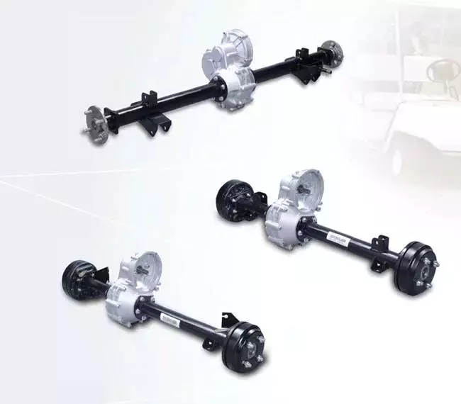
Axles

Types of axles

Axles are used in various kinds of vehicles. Each type of axle carries a different load. The first kind is called the floating axle, while the second type is called the fixed axle. Both types are commonly used in light-duty vehicles and medium-duty trucks. In addition, there are different types of semi-floating axles. These axles are mainly used in trucks, light-duty pickups, and big SUVs.
A live axle transmits power from an engine to the wheels, while a dead axle does not convey power. A dead axle is also known as a lazy axle. A number of vehicles are fitted with dead axles. These axles are usually installed in front of the driving axle. However, a pusher axle is also a dead axle.
Besides being important for vehicle movement, axles are also important for suspension. These parts transfer the driving torque from the driveshaft to the wheels, which maintains the position of the wheels. They are made of durable steel, and are very hard to bend except in cases of severe impact. There are different types of axles based on their purpose: driving axles transfer engine torque to the wheels and dead axles serve as suspension components.
Floating axles have two deep groove ball bearings at each end, and are often called full floating axles. They are usually mounted in SUVs, and are more durable than regular car axles. They are also relatively inexpensive, and can support large loads. The full floating axle is usually used in heavy-duty trucks, midsize trucks, and four-wheel-drive vehicles.
Another type of axle is called a lift axle. These axles are used in Multi-Axle Vehicles, which have more than four axles. As a result, the vehicle has a greater weight capacity than a normal car. A five-axle truck has a gross vehicle weight of forty-two tons, while its kerb weight is twelve tons. Unloaded, it is therefore equal to 30 tons.
Front axles: The front axles of cars are primarily responsible for steering and processing road shocks. The front axle is made of steel that is 0.4-3% carbon steel and one-to-three percent nickel steel. Its circular or elliptical ends and I-section center help it withstand bending loads during braking. The rear axles are the drive shafts and transmit power from the differential to the rear wheels.
Rear axles are inexpensive. They connect the rear differential and can be purchased for about $150, depending on the make and model of the car. They can be found in many modern vehicles, and are commonly found in front-drive vehicles. These modern vehicles also have axle CV shafts, which are more unique than traditional axles.
In addition to tyres, the axles are responsible for transferring power from the engine to the wheels. An axle can break due to improper maintenance or a car accident, and can affect the performance of a vehicle. A damaged axle will cause it to transfer power slowly. It might also make a clunking or sputtering noise.
Axles

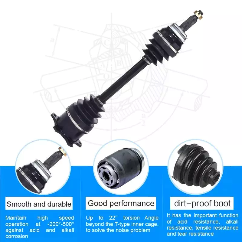
Cost of replacing an axle

Replacing an axle can be a costly task. A car’s axles should last between 35k and 100k miles. However, they can be damaged by hard hits or collisions. Depending on the extent of damage, the car may require a new axle or repair. The cost of an axle repair or replacement depends on several factors, including where the car was hit, the type of car and labor charges.
The cost of replacing an axle can range from around $200 to $900, depending on your vehicle and the type of work involved. Parts can be purchased for under $100 each, but you’ll also need to factor in labor, which can cost up to $200 or more. If you’re replacing both the rear and front axles, the cost will be higher than for just one axle replacement.
Axle repair is a complicated procedure, and the cost varies based on the make and model of your vehicle. A replacement axle will allow wheels to rotate freely. Depending on the severity of the problem, a front axle repair can run between $500 and $800. A rear axle repair will run you about $700.
Although an axle replacement may seem like an expensive and time-consuming task, the process will be less expensive than repairing the whole assembly. Professional mechanics can also replace one axle at a time. If you have a warranty on your car, this can cover the cost of the repair. This is a good way to save money and time while getting your car back on the road.
One of the most common causes of axle failure is the leakage of grease. When grease leaks, the CV joint is left dry, and dirt will get in. Without lubrication, this leads to increased wear, and increases the cost of axle replacement. For this reason, most mechanics will recommend replacing the entire half-shaft instead of just the axle, thereby reducing the cost and the labor time.
Depending on the severity of the damage, replacing an axle can take several hours. Aside from the repair, an alignment may be needed afterward. Most garages include this service with axle work. Depending on the type of alignment, it could cost from $20 to $150+. A complete diagnosis of the vehicle can take up to three hours to complete.
In some cases, a broken axle is completely irreparable. It will damage the rest of the vehicle and may lead to other problems. In such cases, it’s best to take it to a mechanic for repair as soon as possible. In most cases, an axle replacement should be needed just once during the life of the car.
Axles are available in pairs or individually. You can also find them at a junkyard. Installing a new axle is not difficult if you have the proper tools. An impact wrench can help make the job go faster. However, it’s important to have a flat surface for the work and wear safety gear.
Axles

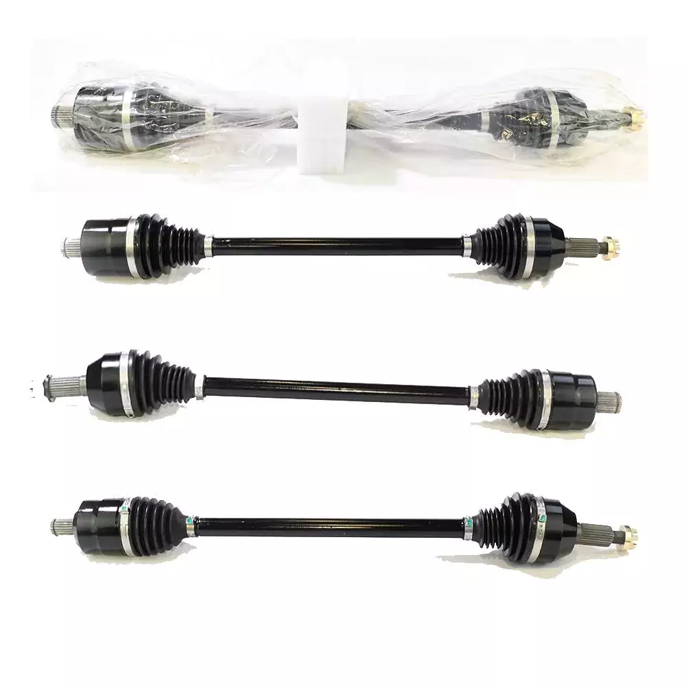
Insurance coverage for repairing an axle

Car insurance may cover the costs of repairing an axle if it’s damaged in an accident, but if the damage occurred because of normal wear and tear, it may not be covered. Similarly, your insurance policy may not cover damage to tires or rims, and it might not cover the costs of a new axle, depending on the condition of the axle.
Your car’s axle is an important part of the vehicle, transferring power from the engine to the wheels. They are built to be durable, but they can bend or break due to a variety of factors, including running over a curb, hitting potholes at high speed, and auto collisions. In such cases, your car may not be able to drive, and a replacement axle may be expensive.
Some of the symptoms of an axle problem are shuddering or clicking sounds when shifting gears. Occasionally, a car may even completely stop. This can lead to an accident or even a loss of control. It’s best to fix an axle before it damages your car in an accident. In some cases, repairing the axle can cost only a few hundred dollars.
You should have your vehicle inspected for signs of wear and tear before repairing an axle. It’s crucial to take your vehicle to a mechanic immediately after an accident, as delayed repairs can lead to further suspension issues. Ideally, your vehicle’s axle should last four to five years or fifty thousand miles, although these numbers can vary. The life of an axle depends on a variety of factors, including the type of driving you do and how often you drive. Driving over rocky or icy surfaces can wear out the protective rubber boot. The rubber can also dry out and crack over time.
While the axle itself is a sturdy component, the parts connected to it are more susceptible to wear and tear. Associated components such as axle bearings are critical to the axle, as they help control the speed of the wheels when they turn. They also help maintain the integrity of the vehicle’s structural system.
Repairing an axle can be expensive, depending on the vehicle’s make and model. Depending on the severity of the problem, the costs of an axle repair can range from $500 to more than $1,000. The cost of an axle repair may also include other necessary repairs. If the damage is caused by normal use, your insurance provider may pay for the costs.
When your vehicle is in need of an axle replacement, it’s a good idea to contact a vehicle repair shop. A vehicle repair shop will give you the best possible estimate of the cost and time to repair the axle.
China Custom cnc machining high precision good quality stainless steel front center axle with hardened treatment     wholesaler China Custom cnc machining high precision good quality stainless steel front center axle with hardened treatment     wholesaler
editor by czh 2023-03-09

China Custom Factory Sale 4 Axis CNC Milling Machine Vmc 850 CNC Vertical Machining Center Vmc650 Vmc400 Vmc320 Vmc1160 with Great quality

Product Description

Product Description

SP8126 NEW 3 4th VMC Vertical cnc metal milling machine center mini small CNC machining center with 800X260MM table Factory direct Sale Sp8126  3 4th Factory Vmc Vertical CNC Metal Milling Machine Center Mini Small CNC Vertical Machining Center with 800X260mm Table VMC550 VMC650 VMC850 VMC1160 factory sale 4 Axis CNC Milling Machine VMC 850 CNC Vertical Machining Center VMC650 VMC400 VMC320 VMC1160
(VMC from small to big size, the web pages are limited, so please contact us for more details)

As 1 new product of independent design & development, SMC8450 is a multi-purpose machine which could mill surface & drill holes. This machine adopts domestic/overseas branded numerical control system and realizes full-screen edition in Chinese. Spindle adopts imported frequency converters, which could fulfill variable speed control & constant linear speed cutting functions; machining body adopts ultrasonic frequency hardening treatment; both X-axle & Z-axle adopts step/servo motor, which could process feeding motion by directly connecting shaft coupling & ball screws.

With high power, pleasant rigidity, high precision & storage, high price-quality ratio and long cycle life, the machine is widely applied to instruments, meters, light industries, electronics, home appliances, medical instruments, aeronautics & astronautics and etc. industries, it is 1 small-medium precision & complex machine for processing various materials (especially non-ferrous metals & stainless steel) as well as an ideal equipments for large automation production.

This machine could process holes below ∮16, milling plane below 18 and milling depth below 3mm.

.

Product Parameters


Model SP8126
Main Motor Power KW 3.7KW
Spindle Max. Rotating Speed Servo Spindle 8000rpm 
Z Motor Torque 7.7N.m
X Motor Torque 6N.m
Y Motor Torque 6N.m
Spindle Taper BT40
Worktable Size 800X260mm
Travel(Longitudinal X/Horizontal Y/Vertical Z) 450X320X450mm
Distance of Spindle Axis to Xihu (West Lake) Dis.way Plane 360mm
Distance of Spindle End to Worktable 90-510mm
The Vertical Permissible Error of Spindle Axis to Worktable Plane ≤0.02mm
Positioning Accuracy 0.02mm
Repeated Positioning Accuracy 0.01mm
Machine Overall Dimension (L*W*H) mm 2600*1950*2400
Machine Net Weight KG 2400
Magazine Capacity 10/12 (Bamboo Hat)
System Configuration Siemens/GSK/Fanuc
External Protection Level Full Closed

Company Profile

As the professional and experienced manufacturer of lathe, mill , drill , cnc and other tools ,ZheJiang SUMORE Industrial Group has been in this filed for more than 20 years.

We have got the certificates of CE certificate . Also we have been in business with GSK ,Siemens ,Faunc and other famous companies within 50 countries all over the world.

Whether you need the standard or the customerised products , please contact us directly . Our professional and experienced engineers and after sale service team will meet your needs.

Hope to cooperate with you!

Analytical Approaches to Estimating Contact Pressures in Spline Couplings

A spline coupling is a type of mechanical connection between 2 rotating shafts. It consists of 2 parts – a coupler and a coupling. Both parts have teeth which engage and transfer loads. However, spline couplings are typically over-dimensioned, which makes them susceptible to fatigue and static behavior. Wear phenomena can also cause the coupling to fail. For this reason, proper spline coupling design is essential for achieving optimum performance.
splineshaft

Modeling a spline coupling

Spline couplings are becoming increasingly popular in the aerospace industry, but they operate in a slightly misaligned state, causing both vibrations and damage to the contact surfaces. To solve this problem, this article offers analytical approaches for estimating the contact pressures in a spline coupling. Specifically, this article compares analytical approaches with pure numerical approaches to demonstrate the benefits of an analytical approach.
To model a spline coupling, first you create the knowledge base for the spline coupling. The knowledge base includes a large number of possible specification values, which are related to each other. If you modify 1 specification, it may lead to a warning for violating another. To make the design valid, you must create a spline coupling model that meets the specified specification values.
After you have modeled the geometry, you must enter the contact pressures of the 2 spline couplings. Then, you need to determine the position of the pitch circle of the spline. In Figure 2, the centre of the male coupling is superposed to that of the female spline. Then, you need to make sure that the alignment meshing distance of the 2 splines is the same.
Once you have the data you need to create a spline coupling model, you can begin by entering the specifications for the interface design. Once you have this data, you need to choose whether to optimize the internal spline or the external spline. You’ll also need to specify the tooth friction coefficient, which is used to determine the stresses in the spline coupling model 20. You should also enter the pilot clearance, which is the clearance between the tip 186 of a tooth 32 on 1 spline and the feature on the mating spline.
After you have entered the desired specifications for the external spline, you can enter the parameters for the internal spline. For example, you can enter the outer diameter limit 154 of the major snap 54 and the minor snap 56 of the internal spline. The values of these parameters are displayed in color-coded boxes on the Spline Inputs and Configuration GUI screen 80. Once the parameters are entered, you’ll be presented with a geometric representation of the spline coupling model 20.

Creating a spline coupling model 20

The spline coupling model 20 is created by a product model software program 10. The software validates the spline coupling model against a knowledge base of configuration-dependent specification constraints and relationships. This report is then input to the ANSYS stress analyzer program. It lists the spline coupling model 20’s geometric configurations and specification values for each feature. The spline coupling model 20 is automatically recreated every time the configuration or performance specifications of the spline coupling model 20 are modified.
The spline coupling model 20 can be configured using the product model software program 10. A user specifies the axial length of the spline stack, which may be zero, or a fixed length. The user also enters a radial mating face 148, if any, and selects a pilot clearance specification value of 14.5 degrees or 30 degrees.
A user can then use the mouse 110 to modify the spline coupling model 20. The spline coupling knowledge base contains a large number of possible specification values and the spline coupling design rule. If the user tries to change a spline coupling model, the model will show a warning about a violation of another specification. In some cases, the modification may invalidate the design.
In the spline coupling model 20, the user enters additional performance requirement specifications. The user chooses the locations where maximum torque is transferred for the internal and external splines 38 and 40. The maximum torque transfer location is determined by the attachment configuration of the hardware to the shafts. Once this is selected, the user can click “Next” to save the model. A preview of the spline coupling model 20 is displayed.
The model 20 is a representation of a spline coupling. The spline specifications are entered in the order and arrangement as specified on the spline coupling model 20 GUI screen. Once the spline coupling specifications are entered, the product model software program 10 will incorporate them into the spline coupling model 20. This is the last step in spline coupling model creation.
splineshaft

Analysing a spline coupling model 20

An analysis of a spline coupling model consists of inputting its configuration and performance specifications. These specifications may be generated from another computer program. The product model software program 10 then uses its internal knowledge base of configuration dependent specification relationships and constraints to create a valid three-dimensional parametric model 20. This model contains information describing the number and types of spline teeth 32, snaps 34, and shoulder 36.
When you are analysing a spline coupling, the software program 10 will include default values for various specifications. The spline coupling model 20 comprises an internal spline 38 and an external spline 40. Each of the splines includes its own set of parameters, such as its depth, width, length, and radii. The external spline 40 will also contain its own set of parameters, such as its orientation.
Upon selecting these parameters, the software program will perform various analyses on the spline coupling model 20. The software program 10 calculates the nominal and maximal tooth bearing stresses and fatigue life of a spline coupling. It will also determine the difference in torsional windup between an internal and an external spline. The output file from the analysis will be a report file containing model configuration and specification data. The output file may also be used by other computer programs for further analysis.
Once these parameters are set, the user enters the design criteria for the spline coupling model 20. In this step, the user specifies the locations of maximum torque transfer for both the external and internal spline 38. The maximum torque transfer location depends on the configuration of the hardware attached to the shafts. The user may enter up to 4 different performance requirement specifications for each spline.
The results of the analysis show that there are 2 phases of spline coupling. The first phase shows a large increase in stress and vibration. The second phase shows a decline in both stress and vibration levels. The third stage shows a constant meshing force between 300N and 320N. This behavior continues for a longer period of time, until the final stage engages with the surface.
splineshaft

Misalignment of a spline coupling

A study aimed to investigate the position of the resultant contact force in a spline coupling engaging teeth under a steady torque and rotating misalignment. The study used numerical methods based on Finite Element Method (FEM) models. It produced numerical results for nominal conditions and parallel offset misalignment. The study considered 2 levels of misalignment – 0.02 mm and 0.08 mm – with different loading levels.
The results showed that the misalignment between the splines and rotors causes a change in the meshing force of the spline-rotor coupling system. Its dynamics is governed by the meshing force of splines. The meshing force of a misaligned spline coupling is related to the rotor-spline coupling system parameters, the transmitting torque, and the dynamic vibration displacement.
Despite the lack of precise measurements, the misalignment of splines is a common problem. This problem is compounded by the fact that splines usually feature backlash. This backlash is the result of the misaligned spline. The authors analyzed several splines, varying pitch diameters, and length/diameter ratios.
A spline coupling is a two-dimensional mechanical system, which has positive backlash. The spline coupling is comprised of a hub and shaft, and has tip-to-root clearances that are larger than the backlash. A form-clearance is sufficient to prevent tip-to-root fillet contact. The torque on the splines is transmitted via friction.
When a spline coupling is misaligned, a torque-biased thrust force is generated. In such a situation, the force can exceed the torque, causing the component to lose its alignment. The two-way transmission of torque and thrust is modeled analytically in the present study. The analytical approach provides solutions that can be integrated into the design process. So, the next time you are faced with a misaligned spline coupling problem, make sure to use an analytical approach!
In this study, the spline coupling is analyzed under nominal conditions without a parallel offset misalignment. The stiffness values obtained are the percentage difference between the nominal pitch diameter and load application diameter. Moreover, the maximum percentage difference in the measured pitch diameter is 1.60% under a torque of 5000 N*m. The other parameter, the pitch angle, is taken into consideration in the calculation.

China Custom Factory Sale 4 Axis CNC Milling Machine Vmc 850 CNC Vertical Machining Center Vmc650 Vmc400 Vmc320 Vmc1160     with Great qualityChina Custom Factory Sale 4 Axis CNC Milling Machine Vmc 850 CNC Vertical Machining Center Vmc650 Vmc400 Vmc320 Vmc1160     with Great quality

China best Economic Cheap CNC Machining Center (China CNC Vertical Milling Machining Center Machine XH7126) with high quality

Product Description

Economic Cheap CNC Machining Center (China CNC Vertical Milling Machining Center Machine XH7126)

Feature :

This machine adopts domestic/overseas branded numerical control system and realizes full-screen edition in Chinese. Spindle adopts imported frequency converters, which could fulfill variable speed control & constant linear speed cutting functions; machining body adopts ultrasonic frequency hardening treatment; both X-axle & Z-axle adopts step/servo motor, which could process feeding motion by directly connecting shaft coupling & ball screws.
With high power, pleasant rigidity, high precision & storage, high price-quality ratio and long cycle life, the machine is widely applied to instruments, meters, light industries, electronics, home appliances, medical instruments, aeronautics & astronautics and etc. industries, it is 1 small-medium precision & complex machine for processing various materials (especially non-ferrous metals & stainless steel) as well as an ideal equipments for large automation production.

Technical Parameter :

Model XH7126
Main Motor Power KW 3.7KW
Spindle Max. Rotating Speed Servo Spindle 6000rpm 
Z Motor Torque 7.7N.m
X Motor Torque 6N.m
Y Motor Torque 6N.m
Spindle Taper BT40
Worktable Size 800X260mm
Travel(Longitudinal X/Horizontal Y/Vertical Z) 450X320X420mm
Distance of Spindle Axis to Xihu (West Lake) Dis.way Plane 360mm
Distance of Spindle End to Worktable 90-510mm
The Vertical Permissible Error of Spindle Axis to Worktable Plane ≤0.02mm
Positioning Accuracy 0.02mm
Repeated Positioning Accuracy 0.01mm
Machine Overall Dimension (L*W*H) mm 2600*1950*2400
Machine Net Weight KG 2400
Magazine Capacity 12 (umbrella type)
System Configuration  
External Protection Full Closed
Controller GSK928

Standard Accessories :

No. Name
1 GSK928 Control System
2 12 tools umbrella type Magazine
3 Linear CZPT way
4 Oil coolant pump
5 Working Lamp
6 Mobile pulse generator
7 Air gun
8 Full closed protection

Stiffness and Torsional Vibration of Spline-Couplings

In this paper, we describe some basic characteristics of spline-coupling and examine its torsional vibration behavior. We also explore the effect of spline misalignment on rotor-spline coupling. These results will assist in the design of improved spline-coupling systems for various applications. The results are presented in Table 1.
splineshaft

Stiffness of spline-coupling

The stiffness of a spline-coupling is a function of the meshing force between the splines in a rotor-spline coupling system and the static vibration displacement. The meshing force depends on the coupling parameters such as the transmitting torque and the spline thickness. It increases nonlinearly with the spline thickness.
A simplified spline-coupling model can be used to evaluate the load distribution of splines under vibration and transient loads. The axle spline sleeve is displaced a z-direction and a resistance moment T is applied to the outer face of the sleeve. This simple model can satisfy a wide range of engineering requirements but may suffer from complex loading conditions. Its asymmetric clearance may affect its engagement behavior and stress distribution patterns.
The results of the simulations show that the maximum vibration acceleration in both Figures 10 and 22 was 3.03 g/s. This results indicate that a misalignment in the circumferential direction increases the instantaneous impact. Asymmetry in the coupling geometry is also found in the meshing. The right-side spline’s teeth mesh tightly while those on the left side are misaligned.
Considering the spline-coupling geometry, a semi-analytical model is used to compute stiffness. This model is a simplified form of a classical spline-coupling model, with submatrices defining the shape and stiffness of the joint. As the design clearance is a known value, the stiffness of a spline-coupling system can be analyzed using the same formula.
The results of the simulations also show that the spline-coupling system can be modeled using MASTA, a high-level commercial CAE tool for transmission analysis. In this case, the spline segments were modeled as a series of spline segments with variable stiffness, which was calculated based on the initial gap between spline teeth. Then, the spline segments were modelled as a series of splines of increasing stiffness, accounting for different manufacturing variations. The resulting analysis of the spline-coupling geometry is compared to those of the finite-element approach.
Despite the high stiffness of a spline-coupling system, the contact status of the contact surfaces often changes. In addition, spline coupling affects the lateral vibration and deformation of the rotor. However, stiffness nonlinearity is not well studied in splined rotors because of the lack of a fully analytical model.
splineshaft

Characteristics of spline-coupling

The study of spline-coupling involves a number of design factors. These include weight, materials, and performance requirements. Weight is particularly important in the aeronautics field. Weight is often an issue for design engineers because materials have varying dimensional stability, weight, and durability. Additionally, space constraints and other configuration restrictions may require the use of spline-couplings in certain applications.
The main parameters to consider for any spline-coupling design are the maximum principal stress, the maldistribution factor, and the maximum tooth-bearing stress. The magnitude of each of these parameters must be smaller than or equal to the external spline diameter, in order to provide stability. The outer diameter of the spline must be at least 4 inches larger than the inner diameter of the spline.
Once the physical design is validated, the spline coupling knowledge base is created. This model is pre-programmed and stores the design parameter signals, including performance and manufacturing constraints. It then compares the parameter values to the design rule signals, and constructs a geometric representation of the spline coupling. A visual model is created from the input signals, and can be manipulated by changing different parameters and specifications.
The stiffness of a spline joint is another important parameter for determining the spline-coupling stiffness. The stiffness distribution of the spline joint affects the rotor’s lateral vibration and deformation. A finite element method is a useful technique for obtaining lateral stiffness of spline joints. This method involves many mesh refinements and requires a high computational cost.
The diameter of the spline-coupling must be large enough to transmit the torque. A spline with a larger diameter may have greater torque-transmitting capacity because it has a smaller circumference. However, the larger diameter of a spline is thinner than the shaft, and the latter may be more suitable if the torque is spread over a greater number of teeth.
Spline-couplings are classified according to their tooth profile along the axial and radial directions. The radial and axial tooth profiles affect the component’s behavior and wear damage. Splines with a crowned tooth profile are prone to angular misalignment. Typically, these spline-couplings are oversized to ensure durability and safety.

Stiffness of spline-coupling in torsional vibration analysis

This article presents a general framework for the study of torsional vibration caused by the stiffness of spline-couplings in aero-engines. It is based on a previous study on spline-couplings. It is characterized by the following 3 factors: bending stiffness, total flexibility, and tangential stiffness. The first criterion is the equivalent diameter of external and internal splines. Both the spline-coupling stiffness and the displacement of splines are evaluated by using the derivative of the total flexibility.
The stiffness of a spline joint can vary based on the distribution of load along the spline. Variables affecting the stiffness of spline joints include the torque level, tooth indexing errors, and misalignment. To explore the effects of these variables, an analytical formula is developed. The method is applicable for various kinds of spline joints, such as splines with multiple components.
Despite the difficulty of calculating spline-coupling stiffness, it is possible to model the contact between the teeth of the shaft and the hub using an analytical approach. This approach helps in determining key magnitudes of coupling operation such as contact peak pressures, reaction moments, and angular momentum. This approach allows for accurate results for spline-couplings and is suitable for both torsional vibration and structural vibration analysis.
The stiffness of spline-coupling is commonly assumed to be rigid in dynamic models. However, various dynamic phenomena associated with spline joints must be captured in high-fidelity drivetrain models. To accomplish this, a general analytical stiffness formulation is proposed based on a semi-analytical spline load distribution model. The resulting stiffness matrix contains radial and tilting stiffness values as well as torsional stiffness. The analysis is further simplified with the blockwise inversion method.
It is essential to consider the torsional vibration of a power transmission system before selecting the coupling. An accurate analysis of torsional vibration is crucial for coupling safety. This article also discusses case studies of spline shaft wear and torsionally-induced failures. The discussion will conclude with the development of a robust and efficient method to simulate these problems in real-life scenarios.
splineshaft

Effect of spline misalignment on rotor-spline coupling

In this study, the effect of spline misalignment in rotor-spline coupling is investigated. The stability boundary and mechanism of rotor instability are analyzed. We find that the meshing force of a misaligned spline coupling increases nonlinearly with spline thickness. The results demonstrate that the misalignment is responsible for the instability of the rotor-spline coupling system.
An intentional spline misalignment is introduced to achieve an interference fit and zero backlash condition. This leads to uneven load distribution among the spline teeth. A further spline misalignment of 50um can result in rotor-spline coupling failure. The maximum tensile root stress shifted to the left under this condition.
Positive spline misalignment increases the gear mesh misalignment. Conversely, negative spline misalignment has no effect. The right-handed spline misalignment is opposite to the helix hand. The high contact area is moved from the center to the left side. In both cases, gear mesh is misaligned due to deflection and tilting of the gear under load.
This variation of the tooth surface is measured as the change in clearance in the transverse plain. The radial and axial clearance values are the same, while the difference between the 2 is less. In addition to the frictional force, the axial clearance of the splines is the same, which increases the gear mesh misalignment. Hence, the same procedure can be used to determine the frictional force of a rotor-spline coupling.
Gear mesh misalignment influences spline-rotor coupling performance. This misalignment changes the distribution of the gear mesh and alters contact and bending stresses. Therefore, it is essential to understand the effects of misalignment in spline couplings. Using a simplified system of helical gear pair, Hong et al. examined the load distribution along the tooth interface of the spline. This misalignment caused the flank contact pattern to change. The misaligned teeth exhibited deflection under load and developed a tilting moment on the gear.
The effect of spline misalignment in rotor-spline couplings is minimized by using a mechanism that reduces backlash. The mechanism comprises cooperably splined male and female members. One member is formed by 2 coaxially aligned splined segments with end surfaces shaped to engage in sliding relationship. The connecting device applies axial loads to these segments, causing them to rotate relative to 1 another.

China best Economic Cheap CNC Machining Center (China CNC Vertical Milling Machining Center Machine XH7126)     with high qualityChina best Economic Cheap CNC Machining Center (China CNC Vertical Milling Machining Center Machine XH7126)     with high quality

China Custom Vertical Machining Center CNC Milling Machine High Precision Vmc (XH7126) near me supplier

Product Description

FEATURES:

XH7126 is a multi-purpose machine which could mill surface & drill holes. This machine adopts domestic/overseas branded numerical control system and realizes full-screen edition in Chinese. Spindle adopts imported frequency converters, which could fulfill variable speed control & constant linear speed cutting functions; machining body adopts ultrasonic frequency hardening treatment; both X-axle & Z-axle adopts step/servo motor, which could process feeding motion by directly connecting shaft coupling & ball screws.

With high power, pleasant rigidity, high precision & storage, high price-quality ratio and long cycle life, the machine is widely applied to instruments, meters, light industries, electronics, home appliances, medical instruments, aeronautics & astronautics and etc. industries, it is 1 small-medium precision & complex machine for processing various materials (especially non-ferrous metals & stainless steel) as well as an ideal equipments for large automation production.

This machine could process holes below ∮16, milling plane below 18 and milling depth below 3mm.

1. X,Y,Z guideway adpot sliding guideway.

2. P5 class flange bearing.

3. ZheJiang tool magazine and linear guideway.

4. Coolant system uses large power pump, guarantee the sufficient lubrication while doing high speed machining.
 

Specification: XH7126
Main Motor Power KW 3.7KW
Spindle Max. Rotating Speed Servo Spindle 8000rpm
Z Motor Torque 7.7N.m
X Motor Torque 6N.m
Y Motor Torque 6N.m
Spindle Taper BT40
Worktable Size 800X260mm
Travel(Longitudinal X/Horizontal Y/Vertical Z) 450X320X450mm
Distance of Spindle Axis to Xihu (West Lake) Dis.way Plane 360mm
Distance of Spindle End to Worktable 90-510mm
The Vertical Permissible Error of Spindle Axis to Worktable Plane ≤0.02mm
Positioning Accuracy 0.02mm
Repeated Positioning Accuracy 0.01mm
Machine Overall Dimension (L*W*H) 2600*1950*2400mm
Machine Net Weight 2400kg
Magazine Capacity 12pcs

The Functions of Splined Shaft Bearings

Splined shafts are the most common types of bearings for machine tools. They are made of a wide variety of materials, including metals and non-metals such as Delrin and nylon. They are often fabricated to reduce deflection. The tooth profile will become deformed with time, as the shaft is used over a long period of time. Splined shafts are available in a huge range of materials and lengths.

Functions

Splined shafts are used in a variety of applications and industries. They are an effective anti-rotational device, as well as a reliable means of transmitting torque. Other types of shafts are available, including key shafts, but splines are the most convenient for transmitting torque. The following article discusses the functions of splines and why they are a superior choice. Listed below are a few examples of applications and industries in which splines are used.
Splined shafts can be of several styles, depending on the application and mechanical system in question. The differences between splined shaft styles include the design of teeth, overall strength, transfer of rotational concentricity, sliding ability, and misalignment tolerance. Listed below are a few examples of splines, as well as some of their benefits. The difference between these styles is not mutually exclusive; instead, each style has a distinct set of pros and cons.
A splined shaft is a cylindrical shaft with teeth or ridges that correspond to a specific angular position. This allows a shaft to transfer torque while maintaining angular correspondence between tracks. A splined shaft is defined as a cylindrical member with several grooves cut into its circumference. These grooves are equally spaced around the shaft and form a series of projecting keys. These features give the shaft a rounded appearance and allow it to fit perfectly into a grooved cylindrical member.
While the most common applications of splines are for shortening or extending shafts, they can also be used to secure mechanical assemblies. An “involute spline” spline has a groove that is wider than its counterparts. The result is that a splined shaft will resist separation during operation. They are an ideal choice for applications where deflection is an issue.
A spline shaft’s radial torsion load distribution is equally distributed, unless a bevel gear is used. The radial torsion load is evenly distributed and will not exert significant load concentration. If the spline couplings are not aligned correctly, the spline connection can fail quickly, causing significant fretting fatigue and wear. A couple of papers discuss this issue in more detail.
splineshaft

Types

There are many different types of splined shafts. Each type features an evenly spaced helix of grooves on its outer surface. These grooves are either parallel or involute. Their shape allows them to be paired with gears and interchange rotary and linear motion. Splines are often cold-rolled or cut. The latter has increased strength compared to cut spines. These types of shafts are commonly used in applications requiring high strength, accuracy, and smoothness.
Another difference between internal and external splined shafts lies in the manufacturing process. The former is made of wood, while the latter is made of steel or a metal alloy. The process of manufacturing splined shafts involves cutting furrows into the surface of the material. Both processes are expensive and require expert skill. The main advantage of splined shafts is their adaptability to a wide range of applications.
In general, splined shafts are used in machinery where the rotation is transferred to an internal splined member. This member can be a gear or some other rotary device. These types of shafts are often packaged together as a hub assembly. Cleaning and lubricating are essential to the life of these components. If you’re using them on a daily basis, you’ll want to make sure to regularly inspect them.
Crowned splines are usually involute. The teeth of these splines form a spiral pattern. They are used for smaller diameter shafts because they add strength. Involute splines are also used on instrument drives and valve shafts. Serration standards are found in the SAE. Both kinds of splines can also contain a ball bearing for high torque. The difference between the 2 types of splines is the number of teeth on the shaft.
Internal splines have many advantages over external ones. For example, an internal spline shaft can be made using a grinding wheel instead of a CNC machine. It also uses a more accurate and economical process. Furthermore, it allows for a shorter manufacturing cycle, which is essential when splining high-speed machines. In addition, it stabilizes the relative phase between the spline and thread.
splineshaft

Manufacturing methods

There are several methods used to fabricate a splined shaft. Key and splined shafts are constructed from 2 separate parts that are shaped in a synchronized manner to transfer torque uniformly. Hot rolling is 1 method, while cold rolling utilizes low temperatures to form metal. Both methods enhance mechanical properties, surface finishes, and precision. The advantage of cold rolling is its cost-effectiveness.
Cold forming is 1 method, as well as machining and assembling. Cold forming is a unique process that allows the spline to be shaped to the desired shape. The resulting shape provides maximum contact area and torsional strength. Standard splines are available in standard sizes, but custom lengths can also be ordered. CZPT offers various auxiliary equipment, such as mating sleeves and flanged bushings.
Cold forging is another method. This method produces long splined shafts that are used in automobile propellers. After the spline portion is cut out, it is worked on in a hobbing machine. Work hardening enhances the root strength of the splined portion. It can be used for bearings, gears, and other mechanical components. Listed below are the manufacturing methods for splined shafts.
Parallel splines are the simplest of the splined shaft manufacturing methods. Parallel splines are usually welded to shafts, while involute splines are made of metal or non-metals. Splines are available in a wide variety of lengths and materials. The process is usually accompanied by a process called milling. The workpiece rotates to produce the serrated surface.
Splines are internal or external grooves in a splined shaft. They work in combination with keyways to transfer torque. Male and female splines are used in gears. Female and male splines correspond to 1 another to ensure proper angular correspondence. Involute splines have more surface area and thus are stronger than external splines. Moreover, they help the shaft fit into a grooved cylindrical member without misalignment.
A variety of other methods of manufacturing a splined shaft can be used to produce a splined shaft. Spline shafts can be produced using broaching and shaping, 2 precision machining methods. Broaching uses a metal tool with successively larger teeth to remove metal and create ridges and holes in the surface of a material. However, this process is expensive and requires special expertise.
splineshaft

Applications

The splined shaft is a mechanical component with a helix-like shape formed by the equal spacing of grooves in a circular ring. The splines can either have parallel or involute sides. The splines minimize stress concentration in stationary joints and can be used in both rotary and linear motion. In some cases, splines are rolled rather than cut. The latter is more durable than cut splines and is often used in applications requiring high strength, accuracy, and smooth finish.
Splined shafts are commonly made of carbon steel. This alloy steel has a low carbon content, making it easy to work with. Carbon steel is a great choice for splines because it is malleable. Generally, high-quality carbon steel provides a consistent motion. Steel alloys are also available that contain nickel, chromium, copper, and other metals. If you’re unsure of the right material for your application, you can consult a spline chart.
Splines are a versatile mechanical component. They are easy to cut and fit. Splines can be internal or external, with teeth positioned at equal intervals on both sides of the shaft. This allows the shaft to engage with the hub around the entire circumference of the hub. It also increases load capacity by creating a constant multiple-tooth point of contact with the hub. For this reason, they’re used extensively in rotary and linear motion.
Splined shafts are used in a wide variety of industries. CZPT Inc. offers custom and standard splined shafts for a variety of applications. When choosing a splined shaft for a specific application, consider the surrounding mated components, torque requirements, and size requirements. These 3 factors will make it the ideal choice for your rotary equipment. And you’ll be pleased with the end result!
There are many types of splines and their applications are endless. They transfer torque and angular misalignment between parts, and they also enable the axial rotation of assembled components. Therefore, splines are an essential component of machinery and are used in a wide range of applications. This type of shaft can be found in various types of machines, from household appliances to industrial machinery. So, the next time you’re looking for a splined shaft, make sure you look for a splined one.

China Custom Vertical Machining Center CNC Milling Machine High Precision Vmc (XH7126)     near me supplier China Custom Vertical Machining Center CNC Milling Machine High Precision Vmc (XH7126)     near me supplier

China Custom 4 5 Axis CNC Milling Machine Manufacturer 7126 Vertical Machining Center Sp8126 near me manufacturer

Product Description

Product Description

SP8126 4 5 axis cnc milling machine manufacturer 7126 vertical machining center  NEW 3 4th VMC Vertical cnc metal milling machine center mini small CNC machining center with 800X260MM table Factory direct Sale High Precision Small VMC Vertical CNC Machining Center New Condition Automatic Smallest 4 Axis Vertical CNC Milling Center Machine SMC8450
(VMC from small to big size, the web pages are limited, so please contact us for more details)

As 1 new product of independent design & development, SMC8450 is a multi-purpose machine which could mill surface & drill holes. This machine adopts domestic/overseas branded numerical control system and realizes full-screen edition in Chinese. Spindle adopts imported frequency converters, which could fulfill variable speed control & constant linear speed cutting functions; machining body adopts ultrasonic frequency hardening treatment; both X-axle & Z-axle adopts step/servo motor, which could process feeding motion by directly connecting shaft coupling & ball screws.

With high power, pleasant rigidity, high precision & storage, high price-quality ratio and long cycle life, the machine is widely applied to instruments, meters, light industries, electronics, home appliances, medical instruments, aeronautics & astronautics and etc. industries, it is 1 small-medium precision & complex machine for processing various materials (especially non-ferrous metals & stainless steel) as well as an ideal equipments for large automation production.

This machine could process holes below ∮16, milling plane below 18 and milling depth below 3mm.

.

Product Parameters

Model SMC8450
Worktable Size 800X260mm
Travel(Longitudinal X/Horizontal Y/Vertical Z) 500X320X450mm
Main Motor Power   3.7KW
Spindle Max. Rotating Speed Servo Spindle 6000rpm (optional 8000rpm 10000rpm)
Z Motor Torque 7.7N.m
X Motor Torque 6N.m
Y Motor Torque 6N.m
Spindle Taper BT40
Distance of Spindle Axis to Xihu (West Lake) Dis.way Plane 360mm
Distance of Spindle End to Worktable 90-470mm
The Vertical Permissible Error of Spindle Axis to Worktable Plane ≤0.02mm
Positioning Accuracy 0.01mm
Repeated Positioning Accuracy 0.02mm
Machine Overall Dimension   2600*1950*2400mm
Net/Gross Weight 2200/2300kgs
Packing size 2270x1880x2500mm

Company Profile

As the professional and experienced manufacturer of lathe, mill , drill , cnc and other tools ,ZheJiang SUMORE Industrial Group has been in this filed for more than 20 years.

We have got the certificates of CE, GS ,Rohs , CSA ,UL ,etc . Also we have been in business with GSK ,Siemens ,Faunc and other famous companies within 50 countries all over the world.

Whether you need the standard or the customerised products , please contact us directly . Our professional and experienced engineers and after sale service team will meet your needs.

Hope to cooperate with you!

Types of Splines

There are 4 types of splines: Involute, Parallel key, helical, and ball. Learn about their characteristics. And, if you’re not sure what they are, you can always request a quotation. These splines are commonly used for building special machinery, repair jobs, and other applications. The CZPT Manufacturing Company manufactures these shafts. It is a specialty manufacturer and we welcome your business.
splineshaft

Involute splines

The involute spline provides a more rigid and durable structure, and is available in a variety of diameters and spline counts. Generally, steel, carbon steel, or titanium are used as raw materials. Other materials, such as carbon fiber, may be suitable. However, titanium can be difficult to produce, so some manufacturers make splines using other constituents.
When splines are used in shafts, they prevent parts from separating during operation. These features make them an ideal choice for securing mechanical assemblies. Splines with inward-curving grooves do not have sharp corners and are therefore less likely to break or separate while they are in operation. These properties help them to withstand high-speed operations, such as braking, accelerating, and reversing.
A male spline is fitted with an externally-oriented face, and a female spline is inserted through the center. The teeth of the male spline typically have chamfered tips to provide clearance with the transition area. The radii and width of the teeth of a male spline are typically larger than those of a female spline. These specifications are specified in ANSI or DIN design manuals.
The effective tooth thickness of a spline depends on the involute profile error and the lead error. Also, the spacing of the spline teeth and keyways can affect the effective tooth thickness. Involute splines in a splined shaft are designed so that at least 25 percent of the spline teeth engage during coupling, which results in a uniform distribution of load and wear on the spline.

Parallel key splines

A parallel splined shaft has a helix of equal-sized grooves around its circumference. These grooves are generally parallel or involute. Splines minimize stress concentrations in stationary joints and allow linear and rotary motion. Splines may be cut or cold-rolled. Cold-rolled splines have more strength than cut spines and are often used in applications that require high strength, accuracy, and a smooth surface.
A parallel key splined shaft features grooves and keys that are parallel to the axis of the shaft. This design is best suited for applications where load bearing is a primary concern and a smooth motion is needed. A parallel key splined shaft can be made from alloy steels, which are iron-based alloys that may also contain chromium, nickel, molybdenum, copper, or other alloying materials.
A splined shaft can be used to transmit torque and provide anti-rotation when operating as a linear guide. These shafts have square profiles that match up with grooves in a mating piece and transmit torque and rotation. They can also be easily changed in length, and are commonly used in aerospace. Its reliability and fatigue life make it an excellent choice for many applications.
The main difference between a parallel key splined shaft and a keyed shaft is that the former offers more flexibility. They lack slots, which reduce torque-transmitting capacity. Splines offer equal load distribution along the gear teeth, which translates into a longer fatigue life for the shaft. In agricultural applications, shaft life is essential. Agricultural equipment, for example, requires the ability to function at high speeds for extended periods of time.
splineshaft

Involute helical splines

Involute splines are a common design for splined shafts. They are the most commonly used type of splined shaft and feature equal spacing among their teeth. The teeth of this design are also shorter than those of the parallel spline shaft, reducing stress concentration. These splines can be used to transmit power to floating or permanently fixed gears, and reduce stress concentrations in the stationary joint. Involute splines are the most common type of splined shaft, and are widely used for a variety of applications in automotive, machine tools, and more.
Involute helical spline shafts are ideal for applications involving axial motion and rotation. They allow for face coupling engagement and disengagement. This design also allows for a larger diameter than a parallel spline shaft. The result is a highly efficient gearbox. Besides being durable, splines can also be used for other applications involving torque and energy transfer.
A new statistical model can be used to determine the number of teeth that engage for a given load. These splines are characterized by a tight fit at the major diameters, thereby transferring concentricity from the shaft to the female spline. A male spline has chamfered tips for clearance with the transition area. ANSI and DIN design manuals specify the different classes of fit.
The design of involute helical splines is similar to that of gears, and their ridges or teeth are matched with the corresponding grooves in a mating piece. It enables torque and rotation to be transferred to a mate piece while maintaining alignment of the 2 components. Different types of splines are used in different applications. Different splines can have different levels of tooth height.

Involute ball splines

When splines are used, they allow the shaft and hub to engage evenly over the shaft’s entire circumference. Because the teeth are evenly spaced, the load that they can transfer is uniform and their position is always the same regardless of shaft length. Whether the shaft is used to transmit torque or to transmit power, splines are a great choice. They provide maximum strength and allow for linear or rotary motion.
There are 3 basic types of splines: helical, crown, and ball. Crown splines feature equally spaced grooves. Crown splines feature involute sides and parallel sides. Helical splines use involute teeth and are often used in small diameter shafts. Ball splines contain a ball bearing inside the splined shaft to facilitate rotary motion and minimize stress concentration in stationary joints.
The 2 types of splines are classified under the ANSI classes of fit. Fillet root splines have teeth that mesh along the longitudinal axis of rotation. Flat root splines have similar teeth, but are intended to optimize strength for short-term use. Both types of splines are important for ensuring the shaft aligns properly and is not misaligned.
The friction coefficient of the hub is a complex process. When the hub is off-center, the center moves in predictable but irregular motion. Moreover, when the shaft is centered, the center may oscillate between being centered and being off-center. To compensate for this, the torque must be adequate to keep the shaft in its axis during all rotation angles. While straight-sided splines provide similar centering, they have lower misalignment load factors.
splineshaft

Keyed shafts

Essentially, splined shafts have teeth or ridges that fit together to transfer torque. Because splines are not as tall as involute gears, they offer uniform torque transfer. Additionally, they provide the opportunity for torque and rotational changes and improve wear resistance. In addition to their durability, splined shafts are popular in the aerospace industry and provide increased reliability and fatigue life.
Keyed shafts are available in different materials, lengths, and diameters. When used in high-power drive applications, they offer higher torque and rotational speeds. The higher torque they produce helps them deliver power to the gearbox. However, they are not as durable as splined shafts, which is why the latter is usually preferred in these applications. And while they’re more expensive, they’re equally effective when it comes to torque delivery.
Parallel keyed shafts have separate profiles and ridges and are used in applications requiring accuracy and precision. Keyed shafts with rolled splines are 35% stronger than cut splines and are used where precision is essential. These splines also have a smooth finish, which can make them a good choice for precision applications. They also work well with gears and other mechanical systems that require accurate torque transfer.
Carbon steel is another material used for splined shafts. Carbon steel is known for its malleability, and its shallow carbon content helps create reliable motion. However, if you’re looking for something more durable, consider ferrous steel. This type contains metals such as nickel, chromium, and molybdenum. And it’s important to remember that carbon steel is not the only material to consider.

China Custom 4 5 Axis CNC Milling Machine Manufacturer 7126 Vertical Machining Center Sp8126     near me manufacturer China Custom 4 5 Axis CNC Milling Machine Manufacturer 7126 Vertical Machining Center Sp8126     near me manufacturer

China best High Precision CNC Machining Center Xk7126 Vertical Machining Center with Best Sales

Product Description

Products Description:
 

CNC Machining Center XK7126 Vertical Machining Center

As 1 new product of independent design & development, XH7126 is a multi-purpose machine which could mill surface
& drill holes. 
This machine adopts domestic/overseas branded numerical control system and realizes full-screen edition in Chinese.
Spindle adopts imported frequency converters, which could fulfill variable speed control & constant linear speed cutting
functions; machining body adopts ultrasonic frequency hardening treatment; both X-axle & Z-axle adopts step/servo motor,
which could process feeding motion by directly connecting shaft coupling & ball screws.
With high power, pleasant rigidity, high precision & storage, high price-quality ratio and long cycle life, the machine is widely
applied to instruments, meters, light industries, electronics, home appliances, medical instruments, aeronautics & astronautics
and etc. industries, it is 1 small-medium precision & complex machine for processing various materials(especially non-ferrous
metals & stainless steel) as well as an ideal equipments for large automation production.This machine could process holes below
∮16, milling plane below 18 and milling depth below 3mm.


Technical Parameter:

Model XH7126
Main Motor Power KW 3.7KW
Spindle Max. Rotating Speed Servo Spindle 6000rpm 
Z Motor Torque 7.7N.m
X Motor Torque 6N.m
Y Motor Torque 6N.m
Spindle Taper BT30
Worktable Size 800X260mm
Travel(Longitudinal X/Horizontal Y/Vertical Z) 450X320X420mm
Distance of Spindle Axis to Xihu (West Lake) Dis.way Plane 360mm
Distance of Spindle End to Worktable 60-480mm
The Vertical Permissible Error of Spindle Axis to Worktable Plane ≤0.02mm
Positioning Accuracy 0.02mm
Repeated Positioning Accuracy 0.01mm
Machine Overall Dimension (L*W*H) mm 2600*1950*2400
Machine Net Weight KG 2400
Magazine Capacity 12 (umbrella type)
External Protection Full Closed
Controller GSK980MDI

Standard accessories:

No. Name
1 GSK980 Control System
2 12 tools umbrella type Magazine
3 Linear CZPT way
4 Oil coolant pump
5 Working Lamp
6 Mobile pulse generator
7 Air gun
8 Full closed protection

Optional accessories:

No. Name
1 Siemens 808D control system
2 Semi-protection


Company Information:

Package & Shipping:
FAQ:

1: What’s your main products of your company?
A : We specialized in all kinds of machines ,such as CNC Lathe Machine ,CNC Milling Machine ,Vertical Machining Center ,Lathe Machines ,Drilling Machine ,
Radial Drilling Machine ,Sawing Machine ,Shaper machine and so on .
2:What kind of controlsdo you use on machines?
A :Siemens,GSK ,Fanuc etc. You can choose according to your requirements .
3. What is your trade terms?
A : FOB, CFR and CIF all acceptable.
4 : How can I choose the most suitable machines ?
A : Please tell me the model or parameter you are interested in, we can provide you with the best price and quality.
You can also send us product pictures and we will choose the most suitable machine for you.
5 : Do we receive any updates while machine is in the manufacturing process?
A : Of course. The progress of the machine will be updated regularly and sent to you.


The Benefits of Spline Couplings for Disc Brake Mounting Interfaces

Spline couplings are commonly used for securing disc brake mounting interfaces. Spline couplings are often used in high-performance vehicles, aeronautics, and many other applications. However, the mechanical benefits of splines are not immediately obvious. Listed below are the benefits of spline couplings. We’ll discuss what these advantages mean for you. Read on to discover how these couplings work.

Disc brake mounting interfaces are splined

There are 2 common disc brake mounting interfaces – splined and six-bolt. Splined rotors fit on splined hubs; six-bolt rotors will need an adapter to fit on six-bolt hubs. The six-bolt method is easier to maintain and may be preferred by many cyclists. If you’re thinking of installing a disc brake system, it is important to know how to choose the right splined and center lock interfaces.
splineshaft

Aerospace applications

The splines used for spline coupling in aircraft are highly complex. While some previous researches have addressed the design of splines, few publications have tackled the problem of misaligned spline coupling. Nevertheless, the accurate results we obtained were obtained using dedicated simulation tools, which are not commercially available. Nevertheless, such tools can provide a useful reference for our approach. It would be beneficial if designers could use simple tools for evaluating contact pressure peaks. Our analytical approach makes it possible to find answers to such questions.
The design of a spline coupling for aerospace applications must be accurate to minimize weight and prevent failure mechanisms. In addition to weight reduction, it is necessary to minimize fretting fatigue. The pressure distribution on the spline coupling teeth is a significant factor in determining its fretting fatigue. Therefore, we use analytical and experimental methods to examine the contact pressure distribution in the axial direction of spline couplings.
The teeth of a spline coupling can be categorized by the type of engagement they provide. This study investigates the position of resultant contact forces in the teeth of a spline coupling when applied to pitch diameter. Using FEM models, numerical results are generated for nominal and parallel offset misalignments. The axial tooth profile determines the behavior of the coupling component and its ability to resist wear. Angular misalignment is also a concern, causing misalignment.
In order to assess wear damage of a spline coupling, we must take into consideration the impact of fretting on the components. This wear is caused by relative motion between the teeth that engage them. The misalignment may be caused by vibrations, cyclical tooth deflection, or angular misalignment. The result of this analysis may help designers improve their spline coupling designs and develop improved performance.
CZPT polyimide, an abrasion-resistant polymer, is a popular choice for high-temperature spline couplings. This material reduces friction and wear, provides a low friction surface, and has a low wear rate. Furthermore, it offers up to 50 times the life of metal on metal spline connections. For these reasons, it is important to choose the right material for your spline coupling.
splineshaft

High-performance vehicles

A spline coupler is a device used to connect splined shafts. A typical spline coupler resembles a short pipe with splines on either end. There are 2 basic types of spline coupling: single and dual spline. One type attaches to a drive shaft, while the other attaches to the gearbox. While spline couplings are typically used in racing, they’re also used for performance problems.
The key challenge in spline couplings is to determine the optimal dimension of spline joints. This is difficult because no commercial codes allow the simulation of misaligned joints, which can destroy components. This article presents analytical approaches to estimating contact pressures in spline connections. The results are comparable with numerical approaches but require special codes to accurately model the coupling operation. This research highlights several important issues and aims to make the application of spline couplings in high-performance vehicles easier.
The stiffness of spline assemblies can be calculated using tooth-like structures. Such splines can be incorporated into the spline joint to produce global stiffness for torsional vibration analysis. Bearing reactions are calculated for a certain level of misalignment. This information can be used to design bearing dimensions and correct misalignment. There are 3 types of spline couplings.
Major diameter fit splines are made with tightly controlled outside diameters. This close fit provides concentricity transfer from the male to the female spline. The teeth of the male spline usually have chamfered tips and clearance with fillet radii. These splines are often manufactured from billet steel or aluminum. These materials are renowned for their strength and uniform grain created by the forging process. ANSI and DIN design manuals define classes of fit.
splineshaft

Disc brake mounting interfaces

A spline coupling for disc brake mounting interfaces is a type of hub-to-brake-disc mount. It is a highly durable coupling mechanism that reduces heat transfer from the disc to the axle hub. The mounting arrangement also isolates the axle hub from direct contact with the disc. It is also designed to minimize the amount of vehicle downtime and maintenance required to maintain proper alignment.
Disc brakes typically have substantial metal-to-metal contact with axle hub splines. The discs are held in place on the hub by intermediate inserts. This metal-to-metal contact also aids in the transfer of brake heat from the brake disc to the axle hub. Spline coupling for disc brake mounting interfaces comprises a mounting ring that is either a threaded or non-threaded spline.
During drag brake experiments, perforated friction blocks filled with various additive materials are introduced. The materials included include Cu-based powder metallurgy material, a composite material, and a Mn-Cu damping alloy. The filling material affects the braking interface’s wear behavior and friction-induced vibration characteristics. Different filling materials produce different types of wear debris and have different wear evolutions. They also differ in their surface morphology.
Disc brake couplings are usually made of 2 different types. The plain and HD versions are interchangeable. The plain version is the simplest to install, while the HD version has multiple components. The two-piece couplings are often installed at the same time, but with different mounting interfaces. You should make sure to purchase the appropriate coupling for your vehicle. These interfaces are a vital component of your vehicle and must be installed correctly for proper operation.
Disc brakes use disc-to-hub elements that help locate the forces and displace them to the rim. These elements are typically made of stainless steel, which increases the cost of manufacturing the disc brake mounting interface. Despite their benefits, however, the high braking force loads they endure are hard on the materials. Moreover, excessive heat transferred to the intermediate elements can adversely affect the fatigue life and long-term strength of the brake system.

China best High Precision CNC Machining Center Xk7126 Vertical Machining Center     with Best SalesChina best High Precision CNC Machining Center Xk7126 Vertical Machining Center     with Best Sales

China Hot selling Hot Sale Vmc600 High Precision CNC Milling Cutting Drilling and Engraving Vertical Machining Center CNC Machine with Free Design Custom

Product Description

Product Description

Product Introduction and Use 
As 1 new product of independent design & development, VMC600 is a multi-purpose machine which could mill surface & drill holes. This machine adopts domestic/overseas branded numerical control system and realizes full-screen edition in Chinese. Spindle adopts imported frequency converters, which could fulfill variable speed control & constant linear speed cutting functions; machining body adopts ultrasonic frequency hardening treatment; both X-axle & Z-axle adopts step/servo motor, which could process feeding motion by directly connecting shaft coupling & ball screws.
With high power, pleasant rigidity, high precision & storage, high price-quality ratio and long cycle life, the machine is widely applied to instruments, meters, light industries, electronics, home appliances, medical instruments, aeronautics & astronautics and etc. industries, it is 1 small-medium precision & complex machine for processing various materials (especially non-ferrous metals & stainless steel) as well as an ideal equipments for large automation production.This machine could process holes below Φ16, milling plane below 18 and milling depth below 3mm.

Detailed Photos


Product Parameters

Major Technical Parameter

  Model VMC600
Main Motor Power KW 5.5KW
Spindle Max. Rotating Speed Servo Spindle 8000rpm
Z Motor Torque 15N.m
X Motor Torque 6N.m
Y Motor Torque 6N.m
Spindle Taper BT40
Worktable Size 800X320mm
Travel(Longitudinal X/Horizontal Y/Vertical Z) 600X400X450mm
Distance of Spindle Axis to Xihu (West Lake) Dis.way Plane 350mm
Distance of Spindle End to Worktable 80-530mm
The Vertical Permissible Error of Spindle Axis to Worktable Plane ≤0.02mm
Positioning Accuracy 0.02mm
Repeated Positioning Accuracy 0.01mm
Machine Overall Dimension (L*W*H) mm 2600*1950*2400
Machine Net Weight KG 2800
System Configuration Siemens 808D/
GSK218/FANUC/mitsubishi M80
External Protection Level Full Closed

Packing List

No. Name Specification Qty.
1 Qualified Certificate VMC600 1
2 Accuracy Inspection List VMC600 1
3 Connection & Test Manual   1
4 User Manual   1
5 Packing List VMC600 1
6 Spanner   1
7 Allen Wrench Set 1
8 Timing Belt   1
9 Milling Chuck BT40 1
10 Drawbar   1
11 Oil Gun   1
12 Iron Cushion   4

List of Partial Sourcing List

No. Name Standard Configuration
1 Ball Screw Jiangshu qijian 
2 Spindle Unit (Optional Accessories) ZheJiang Danquan
3 Electric System Chang’an Electric
4 Oil Pump China South Pump
5 Working Lamp HangZhou CZPT Electric
6 System Siemens,Great, Huazhong, GSK and KND
7 Cylinder (Optional Accessories) HangZhou Xieqing
8 Flange Bearings (P5) Haerbin
9 Tool Magazine ZheJiang DYSO
10 Line CZPT rail ZheJiang HIWIN

Standard Accessories

Spindle unit 8000rpm GSK 218 control system Rigid tapping
ZheJiang HIWIN screw Adjustable block Move the hand vein
Centralized automatic oil lubrication External cooling system and water tank Simple oil-water separation device
Full protection sheet metal shield and rail shield ZheJiang HIWIN linear guideway Tubular work lights, warning lights
12 tools magazine
funnel type
Spindle servo motor:
speed 8000rpm
machine total power 11KW

Optional Accessories

System:Siemens 808D Fanuc 0i-mf Mitsubishi M80
16 tools magazine arm type    

Company Profile


Types of Splines

There are 4 types of splines: Involute, Parallel key, helical, and ball. Learn about their characteristics. And, if you’re not sure what they are, you can always request a quotation. These splines are commonly used for building special machinery, repair jobs, and other applications. The CZPT Manufacturing Company manufactures these shafts. It is a specialty manufacturer and we welcome your business.
splineshaft

Involute splines

The involute spline provides a more rigid and durable structure, and is available in a variety of diameters and spline counts. Generally, steel, carbon steel, or titanium are used as raw materials. Other materials, such as carbon fiber, may be suitable. However, titanium can be difficult to produce, so some manufacturers make splines using other constituents.
When splines are used in shafts, they prevent parts from separating during operation. These features make them an ideal choice for securing mechanical assemblies. Splines with inward-curving grooves do not have sharp corners and are therefore less likely to break or separate while they are in operation. These properties help them to withstand high-speed operations, such as braking, accelerating, and reversing.
A male spline is fitted with an externally-oriented face, and a female spline is inserted through the center. The teeth of the male spline typically have chamfered tips to provide clearance with the transition area. The radii and width of the teeth of a male spline are typically larger than those of a female spline. These specifications are specified in ANSI or DIN design manuals.
The effective tooth thickness of a spline depends on the involute profile error and the lead error. Also, the spacing of the spline teeth and keyways can affect the effective tooth thickness. Involute splines in a splined shaft are designed so that at least 25 percent of the spline teeth engage during coupling, which results in a uniform distribution of load and wear on the spline.

Parallel key splines

A parallel splined shaft has a helix of equal-sized grooves around its circumference. These grooves are generally parallel or involute. Splines minimize stress concentrations in stationary joints and allow linear and rotary motion. Splines may be cut or cold-rolled. Cold-rolled splines have more strength than cut spines and are often used in applications that require high strength, accuracy, and a smooth surface.
A parallel key splined shaft features grooves and keys that are parallel to the axis of the shaft. This design is best suited for applications where load bearing is a primary concern and a smooth motion is needed. A parallel key splined shaft can be made from alloy steels, which are iron-based alloys that may also contain chromium, nickel, molybdenum, copper, or other alloying materials.
A splined shaft can be used to transmit torque and provide anti-rotation when operating as a linear guide. These shafts have square profiles that match up with grooves in a mating piece and transmit torque and rotation. They can also be easily changed in length, and are commonly used in aerospace. Its reliability and fatigue life make it an excellent choice for many applications.
The main difference between a parallel key splined shaft and a keyed shaft is that the former offers more flexibility. They lack slots, which reduce torque-transmitting capacity. Splines offer equal load distribution along the gear teeth, which translates into a longer fatigue life for the shaft. In agricultural applications, shaft life is essential. Agricultural equipment, for example, requires the ability to function at high speeds for extended periods of time.
splineshaft

Involute helical splines

Involute splines are a common design for splined shafts. They are the most commonly used type of splined shaft and feature equal spacing among their teeth. The teeth of this design are also shorter than those of the parallel spline shaft, reducing stress concentration. These splines can be used to transmit power to floating or permanently fixed gears, and reduce stress concentrations in the stationary joint. Involute splines are the most common type of splined shaft, and are widely used for a variety of applications in automotive, machine tools, and more.
Involute helical spline shafts are ideal for applications involving axial motion and rotation. They allow for face coupling engagement and disengagement. This design also allows for a larger diameter than a parallel spline shaft. The result is a highly efficient gearbox. Besides being durable, splines can also be used for other applications involving torque and energy transfer.
A new statistical model can be used to determine the number of teeth that engage for a given load. These splines are characterized by a tight fit at the major diameters, thereby transferring concentricity from the shaft to the female spline. A male spline has chamfered tips for clearance with the transition area. ANSI and DIN design manuals specify the different classes of fit.
The design of involute helical splines is similar to that of gears, and their ridges or teeth are matched with the corresponding grooves in a mating piece. It enables torque and rotation to be transferred to a mate piece while maintaining alignment of the 2 components. Different types of splines are used in different applications. Different splines can have different levels of tooth height.

Involute ball splines

When splines are used, they allow the shaft and hub to engage evenly over the shaft’s entire circumference. Because the teeth are evenly spaced, the load that they can transfer is uniform and their position is always the same regardless of shaft length. Whether the shaft is used to transmit torque or to transmit power, splines are a great choice. They provide maximum strength and allow for linear or rotary motion.
There are 3 basic types of splines: helical, crown, and ball. Crown splines feature equally spaced grooves. Crown splines feature involute sides and parallel sides. Helical splines use involute teeth and are often used in small diameter shafts. Ball splines contain a ball bearing inside the splined shaft to facilitate rotary motion and minimize stress concentration in stationary joints.
The 2 types of splines are classified under the ANSI classes of fit. Fillet root splines have teeth that mesh along the longitudinal axis of rotation. Flat root splines have similar teeth, but are intended to optimize strength for short-term use. Both types of splines are important for ensuring the shaft aligns properly and is not misaligned.
The friction coefficient of the hub is a complex process. When the hub is off-center, the center moves in predictable but irregular motion. Moreover, when the shaft is centered, the center may oscillate between being centered and being off-center. To compensate for this, the torque must be adequate to keep the shaft in its axis during all rotation angles. While straight-sided splines provide similar centering, they have lower misalignment load factors.
splineshaft

Keyed shafts

Essentially, splined shafts have teeth or ridges that fit together to transfer torque. Because splines are not as tall as involute gears, they offer uniform torque transfer. Additionally, they provide the opportunity for torque and rotational changes and improve wear resistance. In addition to their durability, splined shafts are popular in the aerospace industry and provide increased reliability and fatigue life.
Keyed shafts are available in different materials, lengths, and diameters. When used in high-power drive applications, they offer higher torque and rotational speeds. The higher torque they produce helps them deliver power to the gearbox. However, they are not as durable as splined shafts, which is why the latter is usually preferred in these applications. And while they’re more expensive, they’re equally effective when it comes to torque delivery.
Parallel keyed shafts have separate profiles and ridges and are used in applications requiring accuracy and precision. Keyed shafts with rolled splines are 35% stronger than cut splines and are used where precision is essential. These splines also have a smooth finish, which can make them a good choice for precision applications. They also work well with gears and other mechanical systems that require accurate torque transfer.
Carbon steel is another material used for splined shafts. Carbon steel is known for its malleability, and its shallow carbon content helps create reliable motion. However, if you’re looking for something more durable, consider ferrous steel. This type contains metals such as nickel, chromium, and molybdenum. And it’s important to remember that carbon steel is not the only material to consider.

China Hot selling Hot Sale Vmc600 High Precision CNC Milling Cutting Drilling and Engraving Vertical Machining Center CNC Machine     with Free Design CustomChina Hot selling Hot Sale Vmc600 High Precision CNC Milling Cutting Drilling and Engraving Vertical Machining Center CNC Machine     with Free Design Custom