Product Description
Product Details
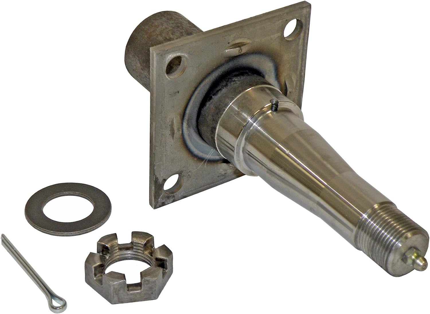
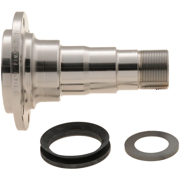
| High Quality CZPT CZPT Gearbox Spindle with Ball Head Assembly | |
| Material | 20CrMnTi or Customized |
| Specifications | According to customer drawing |
| Surface | Rust proofing |
| Tolerance | According to the customer request |
| Customized | We accept customized product. |
| Technology | Advanced Carburizing heat treatment stronger resistance to pressure |
| Application | Applied to the truck chassis system |
| Quality Standard | ISO 9001:2008 Quality system certification |
Product Features
· Accurate size · High tensile strength · Attractive appearance
· Long service life · High cost performance · ISO9001:2008 certificate
Product Picture
Company Other Products
What We Have
· China Leading Producing Technology
· Good Quality
· Competitive Price
· Big Production Ability
· Fast Delivery
· 15 Years’ Production Experience
· Excellent Sale and After-sale Service
· Our products are sold all over the world
FAQ
1. Are you a factory or a trading company?
We are a factory and established in 2003.
2. Is OEM available?
Yes, OEM is available.
3. Is the sample available?
Yes, samples are available for you to test the quality.
4. Are the products tested before shipping?
Yes, all of our products were inspected piece by piece and they are all qualified before shipping.
5. What’s your quality guarantee?
ISO 9001:2008 Quality system authentication
6. What’s benefit will you bring?
· Your clients will be satisfied wih the quality.
· Your clients will continue orders.
· You can get good reputation from your market and obtain more orders.
7. How about the payment terms?
Accept: T/T, L/C, Paypal and etc
8. How to Packing?
We usually use the iron box, Tito’s plate or wooden case,also can be customized according to customer’s packaging requirements.
Contact Us
For more information, pls don’t hesitate to contact us & we are prepared to be challenged, looking forward to get involved in your next project!
/* January 22, 2571 19:08:37 */!function(){function s(e,r){var a,o={};try{e&&e.split(“,”).forEach(function(e,t){e&&(a=e.match(/(.*?):(.*)$/))&&1
| Condition: | New |
|---|---|
| Certification: | ISO9001 |
| Standard: | DIN, ASTM, GB, ANSI |
| Customized: | Customized |
| Material: | 1038,4140 or Customized |
| Application: | Metal Recycling Machine, Metal Cutting Machine, Metal Straightening Machinery, Metal Spinning Machinery, Metal Processing Machinery Parts, Metal forging Machinery, Metal Engraving Machinery, Metal Drawing Machinery, Metal Coating Machinery, Metal Casting Machinery, Auto Parts |
| Samples: |
US$ 30/Piece
1 Piece(Min.Order) | |
|---|
| Customization: |
Available
| Customized Request |
|---|
What are the torque specifications for securing an axle spindle to the suspension components?
The torque specifications for securing an axle spindle to the suspension components can vary depending on the specific vehicle make, model, and year. It’s important to refer to the manufacturer’s documentation or service manual for the accurate torque specifications. Here is a detailed explanation:
When installing or reassembling an axle spindle, it’s crucial to tighten the fasteners to the recommended torque specifications. This ensures proper clamping force and prevents issues such as overtightening, undertightening, or uneven loading. The torque specifications typically include values for the spindle nut, caliper bolts, and other related fasteners.
Since torque specifications can differ among vehicle models and years, it’s best to consult the appropriate manufacturer’s documentation or service manual for the exact torque values. These resources provide detailed information specific to your vehicle, ensuring accurate and safe installation. The documentation may be available in print form from the vehicle manufacturer, or in digital form through online service portals or third-party publications.
When referring to torque specifications, it’s essential to consider the following factors:
- Torque Units: Torque specifications are typically provided in either foot-pounds (ft-lbs) or Newton-meters (Nm). Ensure that you are using the correct unit of measurement to avoid errors.
- Torque Sequence: In some cases, the manufacturer may specify a specific sequence for tightening the fasteners. This sequence ensures even distribution of clamping force and proper alignment of components. Refer to the manufacturer’s documentation for any specified torque sequences.
- Thread Lubrication: Depending on the specific application, the manufacturer may recommend the use of a specific lubricant or thread-locking compound on the fasteners. Follow the manufacturer’s recommendations regarding lubrication to achieve accurate torque values.
- Re-Torqueing: In certain cases, the manufacturer may recommend re-torquing the fasteners after a specific mileage or driving time. This is done to account for any settling or relaxation that may occur in the components. Check the manufacturer’s documentation for any re-torqueing instructions.
It’s worth emphasizing that using the correct torque specifications is crucial to ensure the integrity and safety of the axle spindle and related components. Incorrectly tightened fasteners can lead to issues such as wheel bearing damage, premature wear, or even component failure.
If you are unsure about the torque specifications or lack the necessary tools and expertise, it is recommended to have a qualified mechanic or technician perform the installation or reassembly. They have the knowledge and experience to ensure that the axle spindle is secured with the appropriate torque, following the manufacturer’s specifications.
In summary, the torque specifications for securing an axle spindle to the suspension components vary depending on the vehicle make, model, and year. It is essential to consult the manufacturer’s documentation or service manual for the accurate torque values, taking into account torque units, torque sequence, thread lubrication, and any re-torqueing instructions. When in doubt, seek professional assistance to ensure proper installation and safe operation of the axle spindle.
Can axle spindles be upgraded for improved performance, and if so, what are the options?
Axle spindles can be upgraded to improve the performance of a vehicle, particularly in applications where higher strength, durability, or enhanced capabilities are desired. Upgrading axle spindles can provide benefits such as increased load capacity, improved off-road capability, or enhanced towing capabilities. Here are some options for upgrading axle spindles:
- High-Strength Axle Spindles: One option is to replace the stock axle spindles with high-strength counterparts. High-strength axle spindles are typically made from stronger materials or feature reinforced designs to handle heavier loads or harsher conditions. These upgraded spindles can enhance the overall strength and durability of the axle assembly.
- Performance Axle Spindles: Performance-oriented axle spindles are designed to improve the handling and responsiveness of the vehicle. These spindles may feature optimized geometry, reduced weight, or enhanced stiffness to provide better cornering abilities, reduced body roll, or improved steering precision. Performance axle spindles are commonly used in applications such as racing or high-performance vehicles.
- Off-Road Axle Spindles: Off-road enthusiasts may opt for axle spindles specifically designed for rugged terrains. These spindles often have increased ground clearance, improved articulation, or additional reinforcement to withstand the demands of off-road driving. They can enhance the vehicle’s off-road capability, allowing for traversing challenging obstacles and rough terrain more effectively.
- Towing and Hauling Axle Spindles: Upgraded axle spindles for towing or hauling purposes are engineered to handle heavier loads and provide increased stability. These spindles may have reinforced construction, larger bearings, or specialized features such as integrated trailer brake connections. Upgrading to towing or hauling axle spindles can enhance the vehicle’s towing capacity and improve overall towing performance.
- Custom Axle Spindles: In some cases, custom axle spindles can be fabricated or modified to meet specific performance requirements. This option is typically utilized in specialized vehicle applications or when specific performance goals cannot be achieved with off-the-shelf upgrades. Custom axle spindles allow for tailored solutions that can address unique needs and performance objectives.
When considering axle spindle upgrades, it is essential to ensure compatibility with other components of the axle assembly, such as bearings, hubs, and brakes. Upgrades may also require modifications to other parts of the vehicle, such as suspension systems or steering components, to optimize performance and maintain overall safety and reliability.
It is recommended to consult with knowledgeable professionals, such as experienced mechanics, axle specialists, or vehicle customization experts, to determine the most suitable upgrade options for your specific vehicle and performance goals. They can provide guidance on selecting the appropriate axle spindle upgrades and ensure proper installation and integration into the vehicle’s overall system.
What are the common signs of a worn or faulty axle spindle, and how can they be identified?
A worn or faulty axle spindle can exhibit several common signs that indicate potential issues. Here’s a detailed explanation:
Identifying a worn or faulty axle spindle requires careful observation of the vehicle’s behavior and performance. Here are some common signs that may indicate problems with the axle spindle:
- Uneven Tire Wear: Excessive or uneven tire wear is often a sign of a worn or faulty axle spindle. Inspect the tires regularly and look for patterns of wear, such as excessive wear on the edges, scalloping, cupping, or feathering. Uneven tire wear suggests that the spindle is not properly supporting the wheel assembly or that the alignment is compromised.
- Steering Instability: A worn or faulty axle spindle can cause steering instability. If you notice that the steering feels loose, imprecise, or requires constant correction while driving, it could be a sign of a problem with the spindle. Pay attention to any vibrations or shimmying sensations felt through the steering wheel, as these can also indicate issues with the axle spindle.
- Pulling or Drifting: If the vehicle consistently pulls to one side or drifts off-center, it may be due to a worn or faulty axle spindle. This misalignment can cause uneven tire wear and affect the vehicle’s stability and handling. Keep an eye on the vehicle’s tendency to deviate from a straight path while driving on a level road.
- Noise or Grinding: A worn or faulty axle spindle can produce unusual noises. Listen for any grinding, clicking, or humming sounds coming from the wheel area while driving, especially during turns. These noises may indicate worn or damaged bearings within the spindle assembly, which require immediate attention.
- Excessive Play or Movement: Check for excessive play or movement in the wheel assembly by firmly gripping the tire at the 12 o’clock and 6 o’clock positions and attempting to rock it back and forth. Excessive play or movement can suggest a worn or loose axle spindle, which can compromise the vehicle’s stability and handling.
If you observe any of these signs, it is recommended to have the axle spindle inspected by a qualified mechanic or technician who can assess the condition of the spindle and perform the necessary repairs or replacement.
In addition to visual inspection and observation of the mentioned signs, specialized diagnostic tools may be used to further evaluate the condition of the axle spindle. These tools can measure wheel alignment, detect excessive play or movement, and identify any abnormalities in the spindle assembly.
Regular maintenance and periodic inspections of the suspension system can help in identifying early signs of axle spindle wear or faults. It’s important to address any issues promptly to prevent further damage and ensure the optimal performance and safety of the vehicle.
In summary, common signs of a worn or faulty axle spindle include uneven tire wear, steering instability, pulling or drifting, unusual noises, and excessive play or movement in the wheel assembly. Careful observation, visual inspection, and professional evaluation can help identify these signs and determine the condition of the axle spindle.


editor by CX 2024-05-08
China high quality Auto Car Agricultural Industrial Transmission Spine Spindle Shaft Guiding Driving Forcing Pump Helical Bevel Submersible Pump Bearing Gearbox Helical Teeth Gear with Hot selling
Product Description
Company Profile
Company Profile
HangZhou Xihu (West Lake) Dis. Gain Machinery Co., Ltd., is a manufacture of precision machining from steel plates, castings & closed die forgings. It is founded in 2571 year, covers a total area of about 2000 square meters.
Around 50 people are employed, including 4 engineers.
The company equipped with 10 oblique CZPT CNC Lathes, 35 normal CNC lathes, 6 machining centers, other milling machines and drilling machines.
The Products cover construction parts, auto parts, medical treatment, aerospace, electronics and other fields, exported to Japan, Israel & other Asian countries and Germany, the United States, Canada & other European and American countries.
Certificated by TS16949 quality management system.
Equipment Introduction
Main facility and working range, inspection equipment as follow
| 4 axles CNC Machine Center | 1000mm*600mm*650mm |
| Oblique Xihu (West Lake) Dis. CNC Machine | max φ800mm max length 700mm Tolerance control within 0.01 One time clamping, high accuracy |
| Turning-milling Compound Machining Center | max φ800mm max length 1000mm |
| Other CNC Lathe | Total 30 sets |
| Inspection Equipment | CMM, Projector, CZPT Scale, Micrometer |
| Profiloscope, Hardness tester and so on |
Oblique Xihu (West Lake) Dis. CNC Lathe
Equipped with 10 sets of oblique CZPT CNC Lathes The maximum diameter can be 400-500 mm Precision can reach 0.01mm
Machining Center
6 sets of 4 axles machining center, max SPEC: 1300*70mm, precision can reach 0.01mm
About Products
Quality Control
We always want to be precise, so check dimensions after each production step. We have senior engineers, skilled CNC operator, professional quality inspector. All this makes sure the final goods are high qualified.
Also can do third parity inspection accoring to customer’s reequirments, such as SGS, TUV, ICAS and so on.
Callipers/Height guage
Thread guage
Go/ no go guage
Inside micrometer
Outside micrometer
Micron scale
CMM
Projector
Micrometer
Profiloscope
Hardness tester
Inspection Process
1. Before machining, the engineer will give away the technology card for each process acc. to drawing for quality control.
2. During the machining, the workers will test the dimensions at each step, then marked in the technology card.
3. When machining finished, the professional testing personnel will do 100% retesting again.
Packing Area
In general, the products will be packed in bubble wrap or separated by plywoods firstly.
Then the wrapped products will be put in the wooden cases (no solid wood), which is allowed for export.
Parts can also be packed acc. to customer’s requirement.
Applications of Spline Couplings
A spline coupling is a highly effective means of connecting 2 or more components. These types of couplings are very efficient, as they combine linear motion with rotation, and their efficiency makes them a desirable choice in numerous applications. Read on to learn more about the main characteristics and applications of spline couplings. You will also be able to determine the predicted operation and wear. You can easily design your own couplings by following the steps outlined below.
Optimal design
The spline coupling plays an important role in transmitting torque. It consists of a hub and a shaft with splines that are in surface contact without relative motion. Because they are connected, their angular velocity is the same. The splines can be designed with any profile that minimizes friction. Because they are in contact with each other, the load is not evenly distributed, concentrating on a small area, which can deform the hub surface.
Optimal spline coupling design takes into account several factors, including weight, material characteristics, and performance requirements. In the aeronautics industry, weight is an important design factor. S.A.E. and ANSI tables do not account for weight when calculating the performance requirements of spline couplings. Another critical factor is space. Spline couplings may need to fit in tight spaces, or they may be subject to other configuration constraints.
Optimal design of spline couplers may be characterized by an odd number of teeth. However, this is not always the case. If the external spline’s outer diameter exceeds a certain threshold, the optimal spline coupling model may not be an optimal choice for this application. To optimize a spline coupling for a specific application, the user may need to consider the sizing method that is most appropriate for their application.
Once a design is generated, the next step is to test the resulting spline coupling. The system must check for any design constraints and validate that it can be produced using modern manufacturing techniques. The resulting spline coupling model is then exported to an optimisation tool for further analysis. The method enables a designer to easily manipulate the design of a spline coupling and reduce its weight.
The spline coupling model 20 includes the major structural features of a spline coupling. A product model software program 10 stores default values for each of the spline coupling’s specifications. The resulting spline model is then calculated in accordance with the algorithm used in the present invention. The software allows the designer to enter the spline coupling’s radii, thickness, and orientation.
Characteristics
An important aspect of aero-engine splines is the load distribution among the teeth. The researchers have performed experimental tests and have analyzed the effect of lubrication conditions on the coupling behavior. Then, they devised a theoretical model using a Ruiz parameter to simulate the actual working conditions of spline couplings. This model explains the wear damage caused by the spline couplings by considering the influence of friction, misalignment, and other conditions that are relevant to the splines’ performance.
In order to design a spline coupling, the user first inputs the design criteria for sizing load carrying sections, including the external spline 40 of the spline coupling model 30. Then, the user specifies torque margin performance requirement specifications, such as the yield limit, plastic buckling, and creep buckling. The software program then automatically calculates the size and configuration of the load carrying sections and the shaft. These specifications are then entered into the model software program 10 as specification values.
Various spline coupling configuration specifications are input on the GUI screen 80. The software program 10 then generates a spline coupling model by storing default values for the various specifications. The user then can manipulate the spline coupling model by modifying its various specifications. The final result will be a computer-aided design that enables designers to optimize spline couplings based on their performance and design specifications.
The spline coupling model software program continually evaluates the validity of spline coupling models for a particular application. For example, if a user enters a data value signal corresponding to a parameter signal, the software compares the value of the signal entered to the corresponding value in the knowledge base. If the values are outside the specifications, a warning message is displayed. Once this comparison is completed, the spline coupling model software program outputs a report with the results.
Various spline coupling design factors include weight, material properties, and performance requirements. Weight is 1 of the most important design factors, particularly in the aeronautics field. ANSI and S.A.E. tables do not consider these factors when calculating the load characteristics of spline couplings. Other design requirements may also restrict the configuration of a spline coupling.
Applications
Spline couplings are a type of mechanical joint that connects 2 rotating shafts. Its 2 parts engage teeth that transfer load. Although splines are commonly over-dimensioned, they are still prone to fatigue and static behavior. These properties also make them prone to wear and tear. Therefore, proper design and selection are vital to minimize wear and tear on splines. There are many applications of spline couplings.
A key design is based on the size of the shaft being joined. This allows for the proper spacing of the keys. A novel method of hobbing allows for the formation of tapered bases without interference, and the root of the keys is concentric with the axis. These features enable for high production rates. Various applications of spline couplings can be found in various industries. To learn more, read on.
FE based methodology can predict the wear rate of spline couplings by including the evolution of the coefficient of friction. This method can predict fretting wear from simple round-on-flat geometry, and has been calibrated with experimental data. The predicted wear rate is reasonable compared to the experimental data. Friction evolution in spline couplings depends on the spline geometry. It is also crucial to consider the lubrication condition of the splines.
Using a spline coupling reduces backlash and ensures proper alignment of mated components. The shaft’s splined tooth form transfers rotation from the splined shaft to the internal splined member, which may be a gear or other rotary device. A spline coupling’s root strength and torque requirements determine the type of spline coupling that should be used.
The spline root is usually flat and has a crown on 1 side. The crowned spline has a symmetrical crown at the centerline of the face-width of the spline. As the spline length decreases toward the ends, the teeth are becoming thinner. The tooth diameter is measured in pitch. This means that the male spline has a flat root and a crowned spline.
Predictability
Spindle couplings are used in rotating machinery to connect 2 shafts. They are composed of 2 parts with teeth that engage each other and transfer load. Spline couplings are commonly over-dimensioned and are prone to static and fatigue behavior. Wear phenomena are also a common problem with splines. To address these issues, it is essential to understand the behavior and predictability of these couplings.
Dynamic behavior of spline-rotor couplings is often unclear, particularly if the system is not integrated with the rotor. For example, when a misalignment is not present, the main response frequency is 1 X-rotating speed. As the misalignment increases, the system starts to vibrate in complex ways. Furthermore, as the shaft orbits depart from the origin, the magnitudes of all the frequencies increase. Thus, research results are useful in determining proper design and troubleshooting of rotor systems.
The model of misaligned spline couplings can be obtained by analyzing the stress-compression relationships between 2 spline pairs. The meshing force model of splines is a function of the system mass, transmitting torque, and dynamic vibration displacement. This model holds when the dynamic vibration displacement is small. Besides, the CZPT stepping integration method is stable and has high efficiency.
The slip distributions are a function of the state of lubrication, coefficient of friction, and loading cycles. The predicted wear depths are well within the range of measured values. These predictions are based on the slip distributions. The methodology predicts increased wear under lightly lubricated conditions, but not under added lubrication. The lubrication condition and coefficient of friction are the key factors determining the wear behavior of splines.


China Custom Power Wheel Planetary Gear Drives Gearbox Speed Reducer with Hydraulic Motors near me shop
Product Description
Power Wheel Planetary Gear Drives Gearbox Speed Reducer With Hydraulic Motors
Power Wheel Planetary Gear Drives
The size of this planetary gear drive is American standard size, which is mainly used in the North American market)
Power Wheel Planetary Gear Drives Superior Performance
EPG planetary drives allow greater flexibility than conventional power train systems and often eliminate the need for components such as drive shafts, axles and chain drives. The many models and styles offered meet a wide range of mobile and industrial application requirements. Single, double and triple reduction ratios can be furnished. In addition, they can be supplied with a variety of motor mounts and inputs which allow them to be used with most makes of hydraulic motors.
Our planetary gearboxes are provided with integral multi disc parking brake and have been designed for direct mounting of
hydraulic plug-in motors. The careful choice of the materials and design allows our EPG planetary drives providing 96 to 98% power transfer efficiency, EPG planetary drives are significantly more efficient than many other types of drives, including differential design planetaries. The rugged, compact design of these drives saves space and provides for a long service life. All models can be furnished with parking brakes. EPG has designed integral B4 series parking brakes in Models 4, 6 and 8. These units provide a very compact planetary drive/parking brake package which are particularly useful in applications where space is limited.
EPG planetary drives deliver the required power for smooth operation and precise control. These units are also fully reversible. Reverse power is easily obtained by reversing rotation of the input. For vehicle applications, the positive traction provided by individually powered wheels results in superior maneuverability and improved ground clearance than conventional drive systems. EPG planetary drives can be an efficient solution for any application where you need to increase torque or reduce speed to achieve usable power. Let EPG planetary drives help you put power in its place.
Power Wheel Planetary Gear Drives Key Features
1. Output Torque Range: 1000 … 14000 N.m
2. Gear Ratios: i=2.5 … 500
3. Gear Unit Versions: In line
4. Output Configuration: Wheel drive, shaft output drive, spindle output drive, swing drive
5. Input Configuration: Adapter for hydraulic motor SAE J 744C, shaft input
6. Hydraulic Brake Input: Hydraulically released parking brake on request.
7. The main size of installation is American standard size, which is suitable for the North American customers.
8. Technical parameters and installation dimensions are same as the Auburn Gear’s Model 3, Model 4, Model 5, Model 6, Model 6B, Model 7, Model 7B, Model 8, Model 8B, and Model 9, which can be replaced with them also.
Related Products
Company Information
The Functions of Splined Shaft Bearings
Splined shafts are the most common types of bearings for machine tools. They are made of a wide variety of materials, including metals and non-metals such as Delrin and nylon. They are often fabricated to reduce deflection. The tooth profile will become deformed with time, as the shaft is used over a long period of time. Splined shafts are available in a huge range of materials and lengths.
Functions
Splined shafts are used in a variety of applications and industries. They are an effective anti-rotational device, as well as a reliable means of transmitting torque. Other types of shafts are available, including key shafts, but splines are the most convenient for transmitting torque. The following article discusses the functions of splines and why they are a superior choice. Listed below are a few examples of applications and industries in which splines are used.
Splined shafts can be of several styles, depending on the application and mechanical system in question. The differences between splined shaft styles include the design of teeth, overall strength, transfer of rotational concentricity, sliding ability, and misalignment tolerance. Listed below are a few examples of splines, as well as some of their benefits. The difference between these styles is not mutually exclusive; instead, each style has a distinct set of pros and cons.
A splined shaft is a cylindrical shaft with teeth or ridges that correspond to a specific angular position. This allows a shaft to transfer torque while maintaining angular correspondence between tracks. A splined shaft is defined as a cylindrical member with several grooves cut into its circumference. These grooves are equally spaced around the shaft and form a series of projecting keys. These features give the shaft a rounded appearance and allow it to fit perfectly into a grooved cylindrical member.
While the most common applications of splines are for shortening or extending shafts, they can also be used to secure mechanical assemblies. An “involute spline” spline has a groove that is wider than its counterparts. The result is that a splined shaft will resist separation during operation. They are an ideal choice for applications where deflection is an issue.
A spline shaft’s radial torsion load distribution is equally distributed, unless a bevel gear is used. The radial torsion load is evenly distributed and will not exert significant load concentration. If the spline couplings are not aligned correctly, the spline connection can fail quickly, causing significant fretting fatigue and wear. A couple of papers discuss this issue in more detail.
Types
There are many different types of splined shafts. Each type features an evenly spaced helix of grooves on its outer surface. These grooves are either parallel or involute. Their shape allows them to be paired with gears and interchange rotary and linear motion. Splines are often cold-rolled or cut. The latter has increased strength compared to cut spines. These types of shafts are commonly used in applications requiring high strength, accuracy, and smoothness.
Another difference between internal and external splined shafts lies in the manufacturing process. The former is made of wood, while the latter is made of steel or a metal alloy. The process of manufacturing splined shafts involves cutting furrows into the surface of the material. Both processes are expensive and require expert skill. The main advantage of splined shafts is their adaptability to a wide range of applications.
In general, splined shafts are used in machinery where the rotation is transferred to an internal splined member. This member can be a gear or some other rotary device. These types of shafts are often packaged together as a hub assembly. Cleaning and lubricating are essential to the life of these components. If you’re using them on a daily basis, you’ll want to make sure to regularly inspect them.
Crowned splines are usually involute. The teeth of these splines form a spiral pattern. They are used for smaller diameter shafts because they add strength. Involute splines are also used on instrument drives and valve shafts. Serration standards are found in the SAE. Both kinds of splines can also contain a ball bearing for high torque. The difference between the 2 types of splines is the number of teeth on the shaft.
Internal splines have many advantages over external ones. For example, an internal spline shaft can be made using a grinding wheel instead of a CNC machine. It also uses a more accurate and economical process. Furthermore, it allows for a shorter manufacturing cycle, which is essential when splining high-speed machines. In addition, it stabilizes the relative phase between the spline and thread.
Manufacturing methods
There are several methods used to fabricate a splined shaft. Key and splined shafts are constructed from 2 separate parts that are shaped in a synchronized manner to transfer torque uniformly. Hot rolling is 1 method, while cold rolling utilizes low temperatures to form metal. Both methods enhance mechanical properties, surface finishes, and precision. The advantage of cold rolling is its cost-effectiveness.
Cold forming is 1 method, as well as machining and assembling. Cold forming is a unique process that allows the spline to be shaped to the desired shape. The resulting shape provides maximum contact area and torsional strength. Standard splines are available in standard sizes, but custom lengths can also be ordered. CZPT offers various auxiliary equipment, such as mating sleeves and flanged bushings.
Cold forging is another method. This method produces long splined shafts that are used in automobile propellers. After the spline portion is cut out, it is worked on in a hobbing machine. Work hardening enhances the root strength of the splined portion. It can be used for bearings, gears, and other mechanical components. Listed below are the manufacturing methods for splined shafts.
Parallel splines are the simplest of the splined shaft manufacturing methods. Parallel splines are usually welded to shafts, while involute splines are made of metal or non-metals. Splines are available in a wide variety of lengths and materials. The process is usually accompanied by a process called milling. The workpiece rotates to produce the serrated surface.
Splines are internal or external grooves in a splined shaft. They work in combination with keyways to transfer torque. Male and female splines are used in gears. Female and male splines correspond to 1 another to ensure proper angular correspondence. Involute splines have more surface area and thus are stronger than external splines. Moreover, they help the shaft fit into a grooved cylindrical member without misalignment.
A variety of other methods of manufacturing a splined shaft can be used to produce a splined shaft. Spline shafts can be produced using broaching and shaping, 2 precision machining methods. Broaching uses a metal tool with successively larger teeth to remove metal and create ridges and holes in the surface of a material. However, this process is expensive and requires special expertise.
Applications
The splined shaft is a mechanical component with a helix-like shape formed by the equal spacing of grooves in a circular ring. The splines can either have parallel or involute sides. The splines minimize stress concentration in stationary joints and can be used in both rotary and linear motion. In some cases, splines are rolled rather than cut. The latter is more durable than cut splines and is often used in applications requiring high strength, accuracy, and smooth finish.
Splined shafts are commonly made of carbon steel. This alloy steel has a low carbon content, making it easy to work with. Carbon steel is a great choice for splines because it is malleable. Generally, high-quality carbon steel provides a consistent motion. Steel alloys are also available that contain nickel, chromium, copper, and other metals. If you’re unsure of the right material for your application, you can consult a spline chart.
Splines are a versatile mechanical component. They are easy to cut and fit. Splines can be internal or external, with teeth positioned at equal intervals on both sides of the shaft. This allows the shaft to engage with the hub around the entire circumference of the hub. It also increases load capacity by creating a constant multiple-tooth point of contact with the hub. For this reason, they’re used extensively in rotary and linear motion.
Splined shafts are used in a wide variety of industries. CZPT Inc. offers custom and standard splined shafts for a variety of applications. When choosing a splined shaft for a specific application, consider the surrounding mated components, torque requirements, and size requirements. These 3 factors will make it the ideal choice for your rotary equipment. And you’ll be pleased with the end result!
There are many types of splines and their applications are endless. They transfer torque and angular misalignment between parts, and they also enable the axial rotation of assembled components. Therefore, splines are an essential component of machinery and are used in a wide range of applications. This type of shaft can be found in various types of machines, from household appliances to industrial machinery. So, the next time you’re looking for a splined shaft, make sure you look for a splined one.
China high quality CZPT CZPT Spare Parts CZPT Heavy Truck Gearbox Factory Price Spindle Mechanism Js180A-1701030 with Great quality
Product Description
Company Profile
ZheJiang Xihu (West Lake) Dis. International trade Co., Ltd. is a new foreign trade company, located in HangZhou, ZheJiang , China, is the production base of China Heavy Truck (HOWO) truck, is the distribution center of heavy truck parts. The company’s business models include sinotruk(HOWO), ZheJiang Automobile, FAW, CZPT and other main engine plants of various models, products involving engine, gearbox, cab, axle, chassis, electrical appliances and other parts of the whole car, also involved in part of the construction machinery accessories. Sales scope covers domestic, Russia, Southeast Asia, West Asia, Central Asia, Africa and other regions. We have professional auto parts and overseas warehouses, and carry out cross-border electronic business with international companies.
ZheJiang Xihu (West Lake) Dis. adhering to the “one-stop” service,cooperate with all kinds of high quality manufacturers in China, with high quality resource supply chain , providing high quality and low price products for foreign buyers and end customers. The company has established a high quality management system, a complete supply chain and a professional technical team, integrating the resources of major factories and cooperating with them, and winning customer recognition with price advantage under the premise of quality assurance. The company has obvious market network advantages, product advantages, technological advantages and cost advantages, and has established a unique corporate culture concept.
ZheJiang Xihu (West Lake) Dis. strives to establish a series of local sales channels, such as brand distribution network, local enterprise unified service and large end customer service. The company also seeks to promote high quality automotive parts worldwide and meet customer needs as much as possible. We are trying to promote our own brand “JINHangZhou”, focusing on high-end quality products and pushing them to the market with good quality.
The company promotes the “Belt and Road” strategy, adheres to the principle of extensive consultation, joint construction and sharing, and cooperates with many domestic and foreign companies.
“Fulfill the service commitment, create a better future” is the common concept of Xihu (West Lake) Dis. company, according to customer requirements for service. To meet the needs of customers is our service tenet; Customer satisfaction is our service goal; Customer recognition is a great achievement for each member.
Honesty and trustworthiness is the foundation of the company, so that honesty and trustworthiness become the stepping CZPT of the company.
A cooperation, a lifelong friend!
Business Scope
Our Advantages
1) Reply your enquiry in 2 working hours.
2) 100% delivery of all same quality.
3) Long lasting working life time.
4) Small order acceptable.
5) Timely delivery
6) Excellent after-sale service
7) Parts center build support for our dealers.
FAQ
Q: Are you a manufacturer or trading company?
A: We are manufacturer.
Q: What to do if I don’t know the part number?
A: If you give us the chassis number or the parts photos, we can provide the correct parts you needed.
Q: Can you supply other spare parts?
A: Yes, of course. As you know, 1 truck has thousands of parts so that we can’t show all of them.
Just tell us more details, we’ll find them for you.
Q: What’s your payment term?
A: 30% T/T in advance, 70% balance before shipment
Q: What’s the delivery time?
A: Most of parts are available in storage. So can delivery in 2 days after payment. For the ones no storage,
can delivery in 7 days. For container delivery, 1 container can finish loading in 10 days.
Packaging & Shipping
Applications of Spline Couplings
A spline coupling is a highly effective means of connecting 2 or more components. These types of couplings are very efficient, as they combine linear motion with rotation, and their efficiency makes them a desirable choice in numerous applications. Read on to learn more about the main characteristics and applications of spline couplings. You will also be able to determine the predicted operation and wear. You can easily design your own couplings by following the steps outlined below.
Optimal design
The spline coupling plays an important role in transmitting torque. It consists of a hub and a shaft with splines that are in surface contact without relative motion. Because they are connected, their angular velocity is the same. The splines can be designed with any profile that minimizes friction. Because they are in contact with each other, the load is not evenly distributed, concentrating on a small area, which can deform the hub surface.
Optimal spline coupling design takes into account several factors, including weight, material characteristics, and performance requirements. In the aeronautics industry, weight is an important design factor. S.A.E. and ANSI tables do not account for weight when calculating the performance requirements of spline couplings. Another critical factor is space. Spline couplings may need to fit in tight spaces, or they may be subject to other configuration constraints.
Optimal design of spline couplers may be characterized by an odd number of teeth. However, this is not always the case. If the external spline’s outer diameter exceeds a certain threshold, the optimal spline coupling model may not be an optimal choice for this application. To optimize a spline coupling for a specific application, the user may need to consider the sizing method that is most appropriate for their application.
Once a design is generated, the next step is to test the resulting spline coupling. The system must check for any design constraints and validate that it can be produced using modern manufacturing techniques. The resulting spline coupling model is then exported to an optimisation tool for further analysis. The method enables a designer to easily manipulate the design of a spline coupling and reduce its weight.
The spline coupling model 20 includes the major structural features of a spline coupling. A product model software program 10 stores default values for each of the spline coupling’s specifications. The resulting spline model is then calculated in accordance with the algorithm used in the present invention. The software allows the designer to enter the spline coupling’s radii, thickness, and orientation.
Characteristics
An important aspect of aero-engine splines is the load distribution among the teeth. The researchers have performed experimental tests and have analyzed the effect of lubrication conditions on the coupling behavior. Then, they devised a theoretical model using a Ruiz parameter to simulate the actual working conditions of spline couplings. This model explains the wear damage caused by the spline couplings by considering the influence of friction, misalignment, and other conditions that are relevant to the splines’ performance.
In order to design a spline coupling, the user first inputs the design criteria for sizing load carrying sections, including the external spline 40 of the spline coupling model 30. Then, the user specifies torque margin performance requirement specifications, such as the yield limit, plastic buckling, and creep buckling. The software program then automatically calculates the size and configuration of the load carrying sections and the shaft. These specifications are then entered into the model software program 10 as specification values.
Various spline coupling configuration specifications are input on the GUI screen 80. The software program 10 then generates a spline coupling model by storing default values for the various specifications. The user then can manipulate the spline coupling model by modifying its various specifications. The final result will be a computer-aided design that enables designers to optimize spline couplings based on their performance and design specifications.
The spline coupling model software program continually evaluates the validity of spline coupling models for a particular application. For example, if a user enters a data value signal corresponding to a parameter signal, the software compares the value of the signal entered to the corresponding value in the knowledge base. If the values are outside the specifications, a warning message is displayed. Once this comparison is completed, the spline coupling model software program outputs a report with the results.
Various spline coupling design factors include weight, material properties, and performance requirements. Weight is 1 of the most important design factors, particularly in the aeronautics field. ANSI and S.A.E. tables do not consider these factors when calculating the load characteristics of spline couplings. Other design requirements may also restrict the configuration of a spline coupling.
Applications
Spline couplings are a type of mechanical joint that connects 2 rotating shafts. Its 2 parts engage teeth that transfer load. Although splines are commonly over-dimensioned, they are still prone to fatigue and static behavior. These properties also make them prone to wear and tear. Therefore, proper design and selection are vital to minimize wear and tear on splines. There are many applications of spline couplings.
A key design is based on the size of the shaft being joined. This allows for the proper spacing of the keys. A novel method of hobbing allows for the formation of tapered bases without interference, and the root of the keys is concentric with the axis. These features enable for high production rates. Various applications of spline couplings can be found in various industries. To learn more, read on.
FE based methodology can predict the wear rate of spline couplings by including the evolution of the coefficient of friction. This method can predict fretting wear from simple round-on-flat geometry, and has been calibrated with experimental data. The predicted wear rate is reasonable compared to the experimental data. Friction evolution in spline couplings depends on the spline geometry. It is also crucial to consider the lubrication condition of the splines.
Using a spline coupling reduces backlash and ensures proper alignment of mated components. The shaft’s splined tooth form transfers rotation from the splined shaft to the internal splined member, which may be a gear or other rotary device. A spline coupling’s root strength and torque requirements determine the type of spline coupling that should be used.
The spline root is usually flat and has a crown on 1 side. The crowned spline has a symmetrical crown at the centerline of the face-width of the spline. As the spline length decreases toward the ends, the teeth are becoming thinner. The tooth diameter is measured in pitch. This means that the male spline has a flat root and a crowned spline.
Predictability
Spindle couplings are used in rotating machinery to connect 2 shafts. They are composed of 2 parts with teeth that engage each other and transfer load. Spline couplings are commonly over-dimensioned and are prone to static and fatigue behavior. Wear phenomena are also a common problem with splines. To address these issues, it is essential to understand the behavior and predictability of these couplings.
Dynamic behavior of spline-rotor couplings is often unclear, particularly if the system is not integrated with the rotor. For example, when a misalignment is not present, the main response frequency is 1 X-rotating speed. As the misalignment increases, the system starts to vibrate in complex ways. Furthermore, as the shaft orbits depart from the origin, the magnitudes of all the frequencies increase. Thus, research results are useful in determining proper design and troubleshooting of rotor systems.
The model of misaligned spline couplings can be obtained by analyzing the stress-compression relationships between 2 spline pairs. The meshing force model of splines is a function of the system mass, transmitting torque, and dynamic vibration displacement. This model holds when the dynamic vibration displacement is small. Besides, the CZPT stepping integration method is stable and has high efficiency.
The slip distributions are a function of the state of lubrication, coefficient of friction, and loading cycles. The predicted wear depths are well within the range of measured values. These predictions are based on the slip distributions. The methodology predicts increased wear under lightly lubricated conditions, but not under added lubrication. The lubrication condition and coefficient of friction are the key factors determining the wear behavior of splines.
China Custom High Torque Parallel shaft Cylindrical Gear Speed Reducer gearbox with Best Sales
Relevant Industries: Energy & Mining
Gearing Arrangement: Helical
Output Torque: 3.2-52000N.m
Input Velocity: 300-1800rpm
Output Velocity: fourteen-280rpm
Solution identify: ZSY Sequence solitary-phase parallel-shaft bevel cylindrical pace reducer
Bearing: NSK
Packing: Plywood Circumstance
Efficiency: Single Stage>90%
Output Design and style: Splined Hollow
Item: Worm Equipment Slew Drive
Packaging Specifics: non-fumigation picket situation for Industrial transmissions ZSY Sequence heavy obligation industrial velocity reducer
Port: HangZhou,ZheJiang
Goods Description Merchandise NameZSY Series single-stage parallel-shaft bevel cylindrical pace reducerSeriesspeed reducerColorCustomer’s demandGear material20CrMnTiH 40CrInput typeInput Flange Advise Items K collection helical-bevel gearbox with hollow shaft for sewing equipment transmissionninety one.8% Response Rate
ZGY sequence suspension gearbox reducer for belt conveyor91.8% Response Price
NMRV series worm gearbox pace reducer deviceninety one.8% Reaction Fee
Our Advantages Firm Profile Pre-Sales Services* Inquiry and consulting assist.
* Sample testing assist.
* Check out our Factory.
Right after-Income Support* Training how to instal the device, education how to use the machine.
* Engineers available to support equipment overseas.
Certifications Merchandise packaging PackagingShippingby sea, by air or othersWeightaccording to productPackaging DetailsThe typical deal is picket box or pack it in accordance to customers specific ask for. FAQ 1. How to select a gearbox which satisfies our need?You can refer to our catalogue to choose the gearbox or we can help to decide on when you givethe complex data of needed output torque, output speed and motor parameter etc.2. What details shall we give prior to inserting a obtain order?a) Variety of the gearbox, stainless steel gate track roller wheel 201 304 stainless steel automatic gate pulley wheel with leading mounted plate ratio, input and output type, enter flange, mounting position, and motor informationetc.b) Housing colour.c) Buy amount.d) Other specific needs.3. What industries are your gearboxes being utilised?Our gearboxes are extensively utilised in the regions of textile, meals processing, EPX Front still left Axle Driving Shaft for Lexus Axle Shaft for CZPT Camry Highlander OEM 43420-33200 43420-0E571 beverage, chemical sector,escalator,automated storage equipment, metallurgy, tabacco, Sizzling marketing Large precision planetary gearbox planetary gearbox nema 42 helical equipment reducer DD115-005-B1-S2 for Robotic arm environmental defense, logistics and and many others.4. Doyou promote motors?We have secure motor suppliers who have been coperating with us for a lengthy-time. They can offer motorswith high quality.
Driveshaft framework and vibrations associated with it
The framework of the generate shaft is essential to its efficiency and dependability. Push shafts generally have claw couplings, rag joints and universal joints. Other travel shafts have prismatic or splined joints. Learn about the various types of travel shafts and how they operate. If you want to know the vibrations connected with them, read on. But first, let us define what a driveshaft is.
transmission shaft
As the need on our automobiles continues to enhance, so does the demand on our drive methods. Increased CO2 emission expectations and stricter emission requirements increase the anxiety on the generate system while improving ease and comfort and shortening the turning radius. These and other negative outcomes can spot significant stress and wear on parts, which can guide to driveshaft failure and enhance motor vehicle basic safety hazards. As a result, the drive shaft should be inspected and replaced routinely.
Dependent on your product, you might only need to have to substitute one driveshaft. Even so, the value to change the two driveshafts ranges from $650 to $1850. Furthermore, you might incur labor charges ranging from $one hundred forty to $250. The labor price will depend on your automobile product and its drivetrain variety. In common, nevertheless, the cost of replacing a driveshaft ranges from $470 to $1850.
Regionally, the automotive driveshaft market place can be divided into four key marketplaces: North The us, Europe, Asia Pacific, and Relaxation of the Entire world. North The united states is expected to dominate the market, while Europe and Asia Pacific are predicted to expand the swiftest. Additionally, the market is envisioned to increase at the maximum charge in the future, pushed by economic development in the Asia Pacific area. Furthermore, most of the automobiles sold globally are developed in these locations.
The most essential attribute of the driveshaft is to transfer the electrical power of the motor to helpful work. Push shafts are also identified as propeller shafts and cardan shafts. In a automobile, a propshaft transfers torque from the engine, transmission, and differential to the front or rear wheels, or the two. Owing to the complexity of driveshaft assemblies, they are critical to car security. In addition to transmitting torque from the engine, they have to also compensate for deflection, angular adjustments and length changes.
type
Diverse varieties of push shafts incorporate helical shafts, equipment shafts, worm shafts, planetary shafts and synchronous shafts. Radial protruding pins on the head supply a rotationally secure relationship. At the very least one bearing has a groove extending alongside its circumferential length that makes it possible for the pin to pass by means of the bearing. There can also be two flanges on every end of the shaft. Relying on the software, the shaft can be set up in the most practical location to purpose.
Propeller shafts are normally manufactured of large-high quality metal with large specific power and modulus. However, they can also be created from superior composite materials such as carbon fiber, Kevlar and fiberglass. Yet another variety of propeller shaft is made of thermoplastic polyamide, which is rigid and has a high power-to-weight ratio. The two drive shafts and screw shafts are employed to travel vehicles, ships and bikes.
Sliding and tubular yokes are frequent parts of push shafts. By design, their angles have to be equivalent or intersect to provide the appropriate angle of operation. Until the doing work angles are equal, the shaft vibrates 2 times per revolution, triggering torsional vibrations. The ideal way to keep away from this is to make sure the two yokes are correctly aligned. Crucially, these factors have the very same working angle to guarantee sleek energy circulation.
The kind of drive shaft varies in accordance to the type of motor. Some are geared, whilst others are non-geared. In some instances, the push shaft is mounted and the motor can rotate and steer. Alternatively, a adaptable shaft can be utilised to manage the pace and route of the generate. In some applications the place linear power transmission is not attainable, versatile shafts are a helpful selection. For example, flexible shafts can be utilized in portable gadgets.
place up
The design of the travel shaft has many positive aspects above bare metal. A shaft that is adaptable in numerous directions is easier to maintain than a shaft that is rigid in other instructions. The shaft entire body and coupling flange can be created of various supplies, and the flange can be produced of a various materials than the primary shaft body. For instance, the coupling flange can be made of metal. The main shaft body is ideally flared on at minimum a single end, and the at the very least a single coupling flange involves a 1st typically frustoconical projection extending into the flared stop of the primary shaft physique.
The normal stiffness of fiber-primarily based shafts is reached by the orientation of parallel fibers along the duration of the shaft. However, the bending stiffness of this shaft is lowered owing to the adjust in fiber orientation. Since the fibers carry on to vacation in the very same route from the very first end to the second conclude, the reinforcement that boosts the torsional stiffness of the shaft is not affected. In distinction, a fiber-based shaft is also flexible simply because it utilizes ribs that are approximately 90 levels from the centerline of the shaft.
In addition to the helical ribs, the push shaft a hundred may possibly also have reinforcing elements. These reinforcing elements maintain the structural integrity of the shaft. These reinforcing factors are named helical ribs. They have ribs on both the outer and inner surfaces. This is to prevent shaft breakage. These components can also be formed to be versatile adequate to accommodate some of the forces generated by the push. Shafts can be created using these methods and created into worm-like drive shafts.
vibration
The most typical result in of travel shaft vibration is poor installation. There are 5 widespread varieties of driveshaft vibration, every related to set up parameters. To prevent this from happening, you ought to recognize what triggers these vibrations and how to fix them. The most typical kinds of vibration are detailed below. This report describes some typical travel shaft vibration options. It may possibly also be advantageous to consider the advice of a professional vibration technician for drive shaft vibration management.
If you’re not positive if the difficulty is the driveshaft or the engine, consider turning on the stereo. Thicker carpet kits can also mask vibrations. However, you need to speak to an specialist as before long as attainable. If vibration persists after vibration-related repairs, the driveshaft requirements to be changed. If the driveshaft is nonetheless under guarantee, you can restore it your self.
CV joints are the most widespread cause of 3rd-purchase driveshaft vibration. If they are binding or fail, they require to be replaced. Alternatively, your CV joints could just be misaligned. If it is loose, you can check the CV connector. One more frequent lead to of generate shaft vibration is inappropriate assembly. Inappropriate alignment of the yokes on equally ends of the shaft can result in them to vibrate.
Incorrect trim top can also cause driveshaft vibration. Right trim top is required to avert drive shaft wobble. Whether or not your automobile is new or aged, you can carry out some basic fixes to lessen troubles. One of these options involves balancing the drive shaft. Initial, use the hose clamps to attach the weights to it. Next, attach an ounce of excess weight to it and spin it. By carrying out this, you minimize the frequency of vibration.
value
The international driveshaft marketplace is anticipated to exceed (xxx) million USD by 2028, expanding at a compound annual progress charge (CAGR) of XX%. Its soaring expansion can be attributed to many variables, including growing urbanization and R&D investments by foremost market place gamers. The report also involves an in-depth investigation of crucial industry trends and their influence on the industry. In addition, the report supplies a comprehensive regional analysis of the Driveshaft Market place.
The cost of replacing the push shaft is dependent on the type of fix required and the trigger of the failure. Typical fix expenses selection from $300 to $750. Rear-wheel generate cars normally cost far more. But entrance-wheel push automobiles price much less than 4-wheel drive cars. You could also select to try repairing the driveshaft oneself. Nevertheless, it is critical to do your analysis and make certain you have the necessary tools and equipment to carry out the work appropriately.
The report also handles the competitive landscape of the Travel Shafts industry. It consists of graphical representations, detailed figures, management procedures, and governance parts. Additionally, it involves a detailed value evaluation. Furthermore, the report presents views on the COVID-19 industry and potential tendencies. The report also offers worthwhile data to assist you choose how to contend in your market. When you purchase a report like this, you are adding reliability to your operate.
A top quality driveshaft can increase your game by guaranteeing distance from the tee and bettering responsiveness. The new materials in the shaft design is lighter, more powerful and more responsive than ever ahead of, so it is getting to be a crucial component of the driver. And there are a assortment of options to suit any spending budget. The major element to think about when buying a shaft is its top quality. Nonetheless, it really is important to note that quality isn’t going to occur inexpensive and you ought to often decide on an axle dependent on what your spending budget can deal with.

