Product Description
| Axle Type | Max Capacity(t) | Track(mm) | Brake(mm) | Spring Seat Installation | Axle Beam(mm) | Centre Distance Of Brake Chamber(mm) | Wheel Fixing | Total Length(mm) | Recommended Wheel | Axle Wright(kg) | ||
| Stud | P.C.D(mm) | H(mm) | ||||||||||
| JS08Y2C15 | 8 | 1850 | 420*150 | ≥1080 | 127 | 428 | 10*M22*1.5 ISO | 335 | 280.8 | ~2145 | 7.5V-20 | 323 |
| JS13Y9C10 | 13 | 1840 | 420*180 | ≥970 | 127 | 380 | 10*M22*1.5 ISO | 335 | 280.8 | ~2180 | 7.5V-20 | 342 |
| JS13F1B10 | 13 | 1840 | 420*180 | ≥930 | 150 | 380 | 10*M22*1.5 ISO | 335 | 280.8 | ~2180 | 7.5V-20 | 340 |
| JS14F1B11 | 14 | 1840 | 420*220 | ≥930 | 150 | 340 | 10*M22*1.5 ISO | 335 | 280.8 | ~2180 | 7.5V-20 | 358 |
| JS15F6B11 | 15 | 1850 | 420*180 | ≥940 | 150 | 390 | 10*M22*1.5 ISO | 335 | 280.8 | ~2200 | 8.0V-20 | 370 |
| JS16F6B11 | 16 | 1850 | 420*220 | ≥940 | 150 | 350 | 10*M22*1.5 ISO | 335 | 280.8 | ~2200 | 8.0V-20 | 388 |
| JS20F8B12 | 20 | 1850 | 420*220 | ≥940 | 150 | 345 | 10*M24*1.5 ISO | 335 | 280.8 | ~2247 | 8.0V-20 | 430 |
| JS25H8B12 | 25 | 1850 | 420*220 | ≥940 | 150 | 340 | 10*M24*1.5 ISO | 335 | 280.8 | ~2215 | 8.0V-20 | 474 |
1.Special heat-treat,low-alloy steel axle beam,it has the vitues of good synthetic performance,strong load ability and lower self
weight;
2.High quality alloy solid iserted spindle,through wholy heat treatment,provide superior fatigue capacity;
3.High performance premium non-asbstos brake linings,extend service life;
4.Easy for ABSinstallation;
5.Camshaft,maching with special seals,can ensure no entry of the grease into the brake drum,more safety;
6.New tight fit hub cap have O rings,high property for sealing;
7.Grease lubricant is supplied by Mobil that lengthens the time of free maintenance;
8.Full range of stud fixing such as ISO,BSF,and JAP,it can meet the requirements of various wheel rims.
Trailer axle is connected with frame through suspension, and wheels are installed at both ends. The function of the trailer axle is to support the load of the car and maintain the normal driving of the car on the road. Spoke axle are widely used by India Africa and central American. It has the advantages of better lubrication effect , small resistance and high speed performance.
Application
Packaging & Shipping
ZheJiang CZPT axle manufacturing co.. ltd. founded in200O is professional factory mainly producing semi-trailer axles,
suspensions and relevant parts in our country. It is located in the famous place of interest ShuipoXihu (West Lake) Dis.. Also built in
Quanpu industrial park where is the production base of trailers.
Jinsheng company is a professional manufacturer integrating the scientific research, design, production and sale.It has a
combination of more than 300 skilled employees. Moreover, its professional designers can orientateaccurately and optimize
designs quickly aimed at technical standard and market demand in different countries andregions.
Jinsheng equips itself with first-class technical quality through reasonable and advanced manufacturing axles,suspensions
and other parts. It has advanced processing technology, first-class production line, domestic andinternational advanced
precision CNC and strict inspection process in order to provide customers with superiorquality of semi-trailer axle assembly,
single point suspension assembly and other relevant parts. Thus all of thesemake CZPT company pass ISO9001:2000
quality system certification in 2003 get TS16949certification in 2007.CZPT company upholds first-class product quality,
competitive prices and attentive services. CZPT brandproducts not only meet the needs at home and abroad, but also
in South-Asia, the Middle East, West Asia, SouthAmerica and so on. Therefore CZPT get a good reputation at home and
abroad.
We expect to create a wonder future with your sincere cooperation and support.
Certifications
FAQ
1. What’s your advantage?
— We are manufacturer, we own professinal technology & quality control team; excellent team for foreign trade plus a rich expertise in trading.
2.Where your export to?
— Our export to America, Netherlands, Germany, Italy, Poland, Hungary, Russia, and other European, Asia and Africa countries.
3. Can you send me samples for testing?
— Certainly! We’d like to provide the samples free of charge, but for the freight, pls kindly bear it.
4.Can you supply OEM ?
— Sure, we always supply customized seveices according to customers’ drawing or samples.
5. How long do you finish a new product?
— Usually 20~35days once all information confirmed.
Remark:
Our payment terms
— 30% by T/T in advance, 70% by T/T before shipment
/* January 22, 2571 19:08:37 */!function(){function s(e,r){var a,o={};try{e&&e.split(“,”).forEach(function(e,t){e&&(a=e.match(/(.*?):(.*)$/))&&1
| After-sales Service: | 24 Hours Online |
|---|---|
| Condition: | New |
| Axle Number: | 2 |
| Application: | Truck/Trailer |
| Certification: | CE, ISO |
| Material: | Steel |
| Samples: |
US$ 500/Piece
1 Piece(Min.Order) | |
|---|
| Customization: |
Available
| Customized Request |
|---|

What are the key differences between live axles and dead axles in vehicle design?
In vehicle design, live axles and dead axles are two different types of axle configurations with distinct characteristics and functions. Here’s a detailed explanation of the key differences between live axles and dead axles:
Live Axles:
A live axle, also known as a solid axle or beam axle, is a type of axle where the wheels on both ends of the axle are connected and rotate together as a single unit. Here are the key features and characteristics of live axles:
- Connected Wheel Movement: In a live axle configuration, the wheels on both ends of the axle are linked together, meaning that any movement or forces applied to one wheel will directly affect the other wheel. This connection provides equal power distribution and torque to both wheels, making it suitable for off-road and heavy-duty applications where maximum traction is required.
- Simple Design: Live axles have a relatively simple design, consisting of a solid beam that connects the wheels. This simplicity makes them durable and capable of withstanding heavy loads and rough terrains.
- Weight and Cost: Live axles tend to be heavier and bulkier compared to other axle configurations, which can impact the overall weight and fuel efficiency of the vehicle. Additionally, the manufacturing and maintenance costs of live axles can be lower due to their simpler design.
- Suspension: In most cases, live axles are used in conjunction with leaf spring or coil spring suspensions. The axle is typically mounted to the vehicle’s chassis using leaf springs or control arms, allowing the axle to move vertically to absorb bumps and provide a smoother ride.
- Off-road Capability: Live axles are commonly used in off-road vehicles, trucks, and heavy-duty applications due to their robustness, durability, and ability to deliver power to both wheels simultaneously, enhancing traction and off-road performance.
Dead Axles:
A dead axle, also known as a dummy axle or non-driven axle, is a type of axle that does not transmit power to the wheels. It is primarily used to provide support and stability to the vehicle. Here are the key features and characteristics of dead axles:
- Independent Wheel Movement: In a dead axle configuration, each wheel operates independently, meaning that the movement or forces applied to one wheel will not affect the other wheel. Each wheel is responsible for its own power delivery and traction.
- Weight Distribution: Dead axles are often used to distribute the weight of the vehicle more evenly, especially in cases where heavy loads need to be carried. By adding an extra axle without driving capability, the weight can be distributed over a larger area, reducing the load on other axles and improving stability.
- Steering: Dead axles are commonly used as front axles in vehicles with rear-wheel drive configurations. They provide support for the front wheels and allow for steering control. The steering is typically achieved through a separate mechanism, such as a steering linkage or a steering gear.
- Reduced Complexity: Dead axles are simpler in design compared to live axles since they do not have the additional components required for power transmission. This simplicity can lead to lower manufacturing and maintenance costs.
- Efficiency and Maneuverability: Dead axles are often used in vehicles where power delivery to all wheels is not necessary, such as trailers, certain types of buses, and some light-duty vehicles. By eliminating the power transmission components, these vehicles can achieve better fuel efficiency and improved maneuverability.
It’s important to note that the choice between live axles and dead axles depends on the specific application, vehicle type, and desired performance characteristics. Vehicle manufacturers consider factors such as load capacity, traction requirements, off-road capability, cost, and fuel efficiency when determining the appropriate axle configuration for a particular vehicle model.

Are there specific maintenance tips to extend the lifespan of my vehicle’s axles?
Maintaining the axles of your vehicle is crucial for ensuring their longevity, performance, and overall safety. Here are some specific maintenance tips to extend the lifespan of your vehicle’s axles:
- Regular Inspection:
- Lubrication:
- Seal Inspection and Replacement:
- Proper Loading and Towing:
- Driving Techniques:
- Regular Wheel Alignment:
- Proper Tire Inflation:
- Service Intervals:
Perform regular visual inspections of the axles to check for any signs of damage, leaks, or excessive wear. Look for cracks, bends, or rust on the axle housing, and inspect the axle shafts, seals, and boots. Early detection of issues can help prevent further damage and costly repairs.
Follow the manufacturer’s recommendations for axle lubrication. Proper lubrication helps reduce friction and wear on the axle components. Regularly check the axle’s lubricant level and quality, and replace it as necessary. Use the recommended lubricant type and viscosity for your specific axle.
Check the axle seals for any signs of leaks, such as fluid accumulation around the axle ends. Leaking seals can allow contaminants to enter the axle assembly, leading to premature wear and damage. Replace worn or damaged seals promptly to maintain proper lubrication and prevent contamination.
Ensure that you do not exceed the weight capacity of your vehicle’s axles. Overloading or towing beyond the recommended limits can put excessive stress on the axles, leading to premature wear or failure. Be mindful of the payload and towing capacity specified by the vehicle manufacturer.
Adopt proper driving techniques to minimize stress on the axles. Avoid sudden acceleration, aggressive cornering, and harsh braking, as these actions can subject the axles to excessive forces. Additionally, be cautious when driving over rough terrain or obstacles to prevent impacts that could damage the axles.
Maintain proper wheel alignment to prevent excessive strain on the axles. Misaligned wheels can put uneven loads on the axles, leading to accelerated wear. Regularly check and adjust the wheel alignment as per the manufacturer’s recommendations.
Ensure that your vehicle’s tires are properly inflated according to the recommended tire pressure. Underinflated or overinflated tires can affect the load distribution on the axles and increase the risk of axle damage. Regularly check and maintain the correct tire pressure.
Follow the recommended service intervals for your vehicle, which may include axle inspections, lubricant changes, and other maintenance tasks. Adhering to these intervals ensures that the axles are properly maintained and any potential issues are addressed in a timely manner.
It’s important to consult your vehicle’s owner’s manual for specific maintenance guidelines and intervals provided by the manufacturer. Additionally, if you notice any unusual noises, vibrations, or handling issues related to the axles, it is advisable to have your vehicle inspected by a qualified mechanic to identify and address any potential axle problems promptly.

Can you explain the importance of axle alignment for vehicle stability and handling?
Axle alignment plays a crucial role in ensuring vehicle stability and handling characteristics. Proper alignment of the axles is essential for maintaining optimal tire contact with the road surface, minimizing tire wear, maximizing traction, and promoting safe and predictable handling. Here are the key reasons why axle alignment is important:
- Tire Wear and Longevity:
- Optimal Traction:
- Steering Response and Stability:
- Reduced Rolling Resistance:
- Vehicle Safety:
Correct axle alignment helps distribute the vehicle’s weight evenly across all four tires. When the axles are properly aligned, the tires wear evenly, reducing the risk of premature tire wear and extending their lifespan. Misaligned axles can cause uneven tire wear patterns, such as excessive wear on the inner or outer edges of the tires, leading to the need for premature tire replacement.
Proper axle alignment ensures that the tires maintain optimal contact with the road surface. When the axles are aligned correctly, the tires can evenly distribute the driving forces, maximizing traction and grip. This is particularly important during acceleration, braking, and cornering, as proper alignment helps prevent tire slippage and improves overall vehicle stability.
Axle alignment directly affects steering response and stability. When the axles are properly aligned, the vehicle responds predictably to driver inputs, providing precise and accurate steering control. Misaligned axles can lead to steering inconsistencies, such as pulling to one side or requiring constant correction, compromising vehicle stability and handling.
Proper axle alignment helps reduce rolling resistance, which is the force required to move the vehicle forward. When the axles are aligned correctly, the tires roll smoothly and effortlessly, minimizing energy loss due to friction. This can contribute to improved fuel efficiency and reduced operating costs.
Correct axle alignment is crucial for ensuring vehicle safety. Misaligned axles can affect the vehicle’s stability, especially during emergency maneuvers or sudden lane changes. Proper alignment helps maintain the intended handling characteristics of the vehicle, reducing the risk of loss of control and improving overall safety.
To achieve proper axle alignment, several key parameters are considered, including camber, toe, and caster angles. Camber refers to the vertical tilt of the wheel when viewed from the front, toe refers to the angle of the wheels in relation to each other when viewed from above, and caster refers to the angle of the steering axis in relation to vertical when viewed from the side. These alignment angles are adjusted to meet the vehicle manufacturer’s specifications and ensure optimal performance.
It’s important to note that factors such as road conditions, driving habits, and vehicle modifications can affect axle alignment over time. Regular maintenance and periodic alignment checks are recommended to ensure that the axles remain properly aligned, promoting vehicle stability, handling, and safety.


editor by CX 2024-05-09
China OEM Trailer Parts Rear Axle Shaft Factory Supply Cheap Price Agriculture Axle Trailer Spindle Trailer Hubs axle for car
Product Description
trailer parts rear axle shaft Factory Supply Cheap Price agriculture axle Trailer spindle trailer hubs
|
item |
value |
|
Place of Origin |
China |
|
Province |
ZheJiang |
|
Model Number |
Customized Services |
|
Process |
Mainly Hot forging, Some parts with Cold forging ,die forging and Free forgin will be OK |
|
Material |
Carbon steel: CM490,A36,1045,1035 etc., Alloy steel: 40Cr, 20CrMnTi, 20CrNiMo, 42CrMo4 etc., Stainless steel, SS304,SS316 etc. |
|
Weight |
1kg – 120kg |
|
Applicable Machining Process |
CNC Machining/ Lathing/ Milling/ Turning/ Boring/ Drilling/ Tapping/ Broaching/Reaming etc. |
|
Machining Tolerance |
0.03mm-0.1mm |
|
Applicable Finish Surface Treatment |
Shot/sand blast, polishing, Surface passivation, Primer Painting , Powder coating, ED- Coating, Chromate Plating, zinc-plate, Dacromat coating, Finish Painting, |
|
Testing equipment |
Supersonic inspection machine, Supersonic flaw detecting machine , physics and chemical analysis. |
|
MOQ of mass production |
1000-5000pcs |
|
Testing equipment |
Optical Spectrum Analyzer,tensile testing machine,impact testing machine,fluorescent magnetic particle detector,hardness tester,ultrasonic flaw detector..etc. |
|
Packing |
Wooden cases or according to customers’ needs |
1. who are we?
We are based in ZheJiang , China, start from 2571,sell to North America(10.00%),South America(10.00%),Southeast
Asia(10.00%),Africa(10.00%),Mid East(10.00%),Eastern Asia(10.00%),Central America(10.00%),Northern Europe(10.00%),South
Asia(10.00%),Domestic Market(10.00%). There are total about 11-50 people in our office.
2. how can we guarantee quality?
Always a pre-production sample before mass production;
Always final Inspection before shipment;
3.what can you buy from us?
semi trailer axles, air suspensions , chamber,wheel ,slack adjuster and other related items.
4. why should you buy from us not from other suppliers?
We have a trailer parts production more than 10 years the supply chain
5. what services can we provide?
Accepted Delivery Terms: FOB,CIF,EXW;
Accepted Payment Currency:USD,EUR,JPY,CAD,AUD,HKD,GBP,CNY,CHF;
Accepted Payment Type: T/T;
Language Spoken:English,Chinese
6.what is the certificate
At present, the company can undertake CCS, ABS, BV, GL and other certification products /* January 22, 2571 19:08:37 */!function(){function s(e,r){var a,o={};try{e&&e.split(“,”).forEach(function(e,t){e&&(a=e.match(/(.*?):(.*)$/))&&1
| After-sales Service: | Available |
|---|---|
| Condition: | New |
| Application: | Trailer |
| Certification: | ASTM, CE, DIN, ISO |
| Material: | Steel |
| Transport Package: | Customized |
| Customization: |
Available
| Customized Request |
|---|
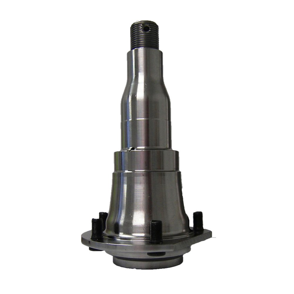
How do I properly inspect an axle spindle for signs of wear or damage?
Inspecting an axle spindle for signs of wear or damage is an important part of vehicle maintenance. Here is a detailed explanation of how to properly inspect an axle spindle:
Before starting the inspection, ensure the vehicle is safely supported on jack stands and the wheels are removed to provide clear access to the axle spindles. Here are the steps to follow:
- Visual Inspection: Begin by visually examining the axle spindle for any visible signs of wear, damage, or irregularities. Look for the following indications:
- Cracks or fractures on the spindle surface
- Bent or warped spindle
- Signs of excessive corrosion or rust
- Visible wear patterns or grooves
- Unusual discoloration or heat marks
- Tactile Inspection: Run your fingers along the surface of the spindle to feel for any roughness, pitting, or other abnormalities. Pay attention to any areas that feel excessively rough or have noticeable imperfections.
- Bearing Play: Check for excessive play or looseness in the wheel bearing by grasping the wheel at the top and bottom and attempting to move it back and forth. If there is noticeable play, it may indicate worn or damaged wheel bearings, which can affect the spindle’s performance.
- Runout Measurement: Using a dial indicator, measure the spindle’s runout. This involves checking for any deviation or wobbling of the spindle when it rotates. Attach the dial indicator to a fixed point on the suspension or brake assembly and position the indicator’s contact point against the spinning spindle. Slowly rotate the spindle and observe the dial indicator’s reading. Excessive runout can indicate a bent or warped spindle.
- Brake Component Alignment: Check the alignment of the brake components, including the brake rotor and caliper, in relation to the spindle. Ensure that the rotor sits flush against the spindle surface and that the caliper is properly aligned with the rotor. Misalignment can indicate a bent or damaged spindle.
- Seal and Bearing Inspection: If possible, remove the wheel bearing and seal to inspect them for any signs of damage, wear, or leakage. Look for pitting, excessive wear, or damaged seals. Replace the bearings and seals if necessary.
It’s important to note that axle spindle inspection may require specialized tools, such as a dial indicator or bearing puller. If you’re uncomfortable performing the inspection yourself or lack the necessary tools, it’s recommended to have a qualified mechanic or technician inspect the spindle for you.
Regular axle spindle inspections can help identify potential issues early on, allowing for timely repairs or replacements. If you notice any signs of wear, damage, or irregularities during the inspection, it’s advisable to consult a professional for further evaluation and necessary repairs.
In summary, properly inspecting an axle spindle involves a visual and tactile examination for signs of wear or damage, checking for bearing play, measuring runout, assessing brake component alignment, and inspecting the wheel bearings and seals. Follow the recommended steps and consider seeking professional assistance if needed.
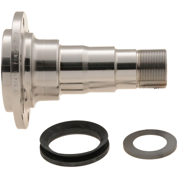
What is the role of grease and lubrication in maintaining a healthy axle spindle?
Grease and lubrication play a crucial role in maintaining a healthy axle spindle. The axle spindle is a vital component of a vehicle’s suspension system, and proper lubrication is essential to ensure its longevity and performance. Here’s why grease and lubrication are important:
- 1. Friction Reduction: One of the primary functions of grease and lubrication is to reduce friction between moving parts. In the axle spindle, there are multiple points of contact where components rotate or slide. Applying grease minimizes friction and heat generation, which can lead to wear and damage if left unchecked.
- 2. Wear Prevention: Grease forms a protective barrier between metal surfaces, preventing direct metal-to-metal contact. This helps prevent wear and damage to the axle spindle and associated components, such as wheel bearings and hubs.
- 3. Corrosion Resistance: Grease serves as a protective layer against moisture and corrosive agents. The axle spindle is exposed to the elements, and moisture or road salt can lead to corrosion. Proper lubrication with grease creates a barrier that inhibits corrosion and extends the spindle’s lifespan.
- 4. Temperature Regulation: Axle spindles can generate heat during operation. Lubrication helps dissipate this heat and maintain the spindle’s temperature within a safe range. Excessive heat can lead to premature component failure.
- 5. Noise Reduction: Properly lubricated axle spindles result in smoother and quieter operation. Inadequate lubrication can cause squeaks, squeals, or other unwanted noises during vehicle operation.
- 6. Enhanced Performance: Well-lubricated axle spindles contribute to the overall performance of the vehicle. They ensure that the wheels rotate freely, providing stability, control, and safe handling.
- 7. Extended Lifespan: Regular maintenance and lubrication can significantly extend the lifespan of the axle spindle and its associated components. This reduces the need for costly replacements and repairs.
Proper lubrication involves selecting the right type of grease or lubricant for the application, as well as adhering to a maintenance schedule that includes cleaning, inspection, and re-greasing as needed. Maintaining a healthy axle spindle through lubrication is essential for the safety and reliability of a vehicle, whether it’s a passenger car, truck, or other heavy-duty vehicle.
How does a damaged or bent axle spindle impact the performance of a vehicle?
A damaged or bent axle spindle can significantly impact the performance and safety of a vehicle. Here’s a detailed explanation:
When the axle spindle is damaged or bent, it can cause various issues that affect the overall performance and handling of the vehicle. Here are some ways a damaged or bent axle spindle can impact a vehicle:
- Wheel Misalignment: A damaged or bent axle spindle can result in wheel misalignment. This misalignment can cause uneven tire wear, reduced traction, and compromised handling. The vehicle may pull to one side, and the steering may feel unstable or imprecise. Wheel misalignment can also lead to increased rolling resistance, negatively impacting fuel efficiency.
- Vibration and Shaking: A bent axle spindle can cause vibrations and shaking in the vehicle, particularly at higher speeds. The imbalance created by the bent spindle can result in uneven tire rotation and wheel wobbling, leading to an uncomfortable and potentially unsafe driving experience.
- Braking Issues: A damaged axle spindle can affect the performance of the braking system. Uneven wheel rotation caused by a bent spindle can result in inconsistent braking force distribution. This can lead to longer braking distances, reduced braking efficiency, and potentially compromised safety in emergency braking situations.
- Suspension Component Stress: A damaged or bent axle spindle can place excessive stress on other suspension components, such as wheel bearings, control arms, or steering linkage. The misalignment and increased forces can accelerate wear and tear on these components, leading to premature failure and costly repairs.
- Handling and Stability: A compromised axle spindle can negatively impact the vehicle’s handling and stability. It can cause unpredictable steering response, reduced cornering ability, and decreased overall stability during maneuvers. This can increase the risk of loss of control and accidents, especially in emergency or evasive driving situations.
It’s important to address a damaged or bent axle spindle promptly. Continuing to drive with a damaged spindle can exacerbate the issues mentioned above and potentially cause further damage to other components of the suspension system. If you suspect a problem with the axle spindle, it’s recommended to have the vehicle inspected by a qualified mechanic or technician who can accurately diagnose the issue and perform the necessary repairs or replacement.
In summary, a damaged or bent axle spindle can have a significant impact on the performance and safety of a vehicle. It can cause wheel misalignment, vibrations, braking issues, stress on suspension components, and compromised handling and stability. Prompt attention and repair are crucial to ensure the vehicle’s optimal performance and to maintain safety on the road.
editor by CX 2024-04-22
China Standard OEM Hot Forging Open Die Forging Carbon Steel and Alloy Steel Forging Shaft Axle CZPT Bar Spindle Forged axle clamp
Product Description
Product Description
Free Forging and Open Die Forging factory for 30 years. ZPMC, NGC and ZheJiang Electric long term stable supplier.
Our Forged Steel Products
Tiangong Forging supplies a variety of semi-finished forged steel products, with the main materials being nickel-molybdenum steel, alloy steel, die steel, stainless steel and carbon steel. In addition to general steel grades such as 35#, 45#, 42CrMo, 42CrMo4, 18CrNiMo7-6, 20CrNi2Mo, 30CrNiMo8 and etc., we can also prepare the required steel according to other national specifications or specified alloy compositions requested by customers.
The maximum production shaft forging length/weight is 12m/15T; the maximum gear and wheel forging diameter/weight is 1.9m/9T.
We are particularly specialized in the forging of special-shaped forging parts.
Our main products:
A.Forged Gear Blank
B.Wheel and Pulley
C.Forged Shaft
D.Hollow Shaft
E.Crankshaft
F.Multi-stepped Shaft
G.Various forged blank and block
I. Special-shaped Forging Parts
Product Parameters
Our open die forging process capabilities include:
|
ITEM |
MAX OD |
MAX HEIGHT |
|
Gear |
120″ |
20″ |
|
ITEM |
MAX OD |
MAX THICKNESS |
|
RECTANGLE / BLOCKS |
20″ |
8,000 |
|
ITEM |
MAX DIAMETER |
MAX LENGTH |
|
SHAFTS |
36″ |
78″ |
|
ITEM |
MAX OD |
MAX LENGTH |
|
CYLINDERS |
50″ |
40″ |
More Products
Production Flow Chart
Certifications
Factory Show
Our company located in HangZhou city, ZheJiang province. Neaby ZheJiang . With over 30 years of forging experience. Our focus is on using high-efficiency electro-hydraulic hammer facilities to produce free forged and open-die forged products.
We are proud of our independent quality assurance laboratory, which ensures that all of our products meet our customers’ requirements.
A. More than 25 years of professional free forging and open-die forging manufacturing experience
B. The company covers an area of 71,000 square meters
C. The construction area of the production workshop is 12,000 square meters
D. Total number of employees: 158
E. 28 engineering and technical personnel
F. 59 skilled workers
G. Annual production capacity is 38,000 tons
H. Annual raw material steel throughput turnover reaches 56,000 tons
Reliable production
At Tiangong Forging, we invest in production equipment every year to maintain and further improve the quality of our products.
The only way to achieve the required quality is to start with a correctly specified material and process it on an efficient forging machine. To ensure the final standards required by our customers, a correct and precisely controlled heat treatment process is a key factor.
Various types of high-precision machining equipment are also an important part of providing products with high customer satisfaction.
- 12 tons Electro-hydraulic Hammer with Operating Machine
- 8 tons Electro-hydraulic Hammer with Operating Machine
- 5 tons Electro-hydraulic Hammer with Operating Machine
- 20 tons Loader
- 5 tons Loader
- Natural Gas Pre-forging Heating Furnace
- Heat Treatment Electric Furnace
- There are 5 heat treatment electric furnaces with loading capacities of 5 tons, 15 tons, 50 tons, 60 tons and 60 tons respectively.
- Various Machining Equipment
- The machining center has multiple high-precision machining equipment such as CNC vertical lathes, CNC horizontal lathes, horizontal milling machines, radial drilling machines, ordinary horizontal lathes, sawing machines, etc
Main Mateirals: Carbon Steel, Stainless Steel and Alloy steels;
International Standards: ASME, JIS, DIN, GB, BS, EN, AS, SABS, etc.
Standardization and Customization are both our advantages.
Application:
Our parts are widely used in Chemical Industry, Wind power generator, Large machinery parts Chemical industry,Agricultural machinery parts ship shaft fittings. Wind Power gearbox Transmission system.
HangZhou Port, HangZhou automatic Port, ZheJiang Yang shan Port, Italy Vado port. ZheJiang Tailway crane, Egypt hanging bridge, Sri Lanka railway crane, Thailand port bridge. South Korea railway crane, Hongkong island bridge, Singapore railway crane, Russia oil & mining machines and some miltary project. etc.
Customized solutions
Our modular process allows us to design solutions various industrial application requiring free-forged and open-die-forged parts. Our modularity means flexibility, wide choice, faster delivery and, above all, competitiveness.
All Tiangong Forging, products and production processes are designed to ensure exceptional, reliable and long-lasting unique mechanical properties, thereby reducing operating costs and extending service life.
With an extensive product range and extensive experience gained in most industrial applications, we can also provide engineering advice to our customers.
Welcome to visit our factory! Welcome to send inquiry to us.
Welcom Trading compamy to co-operate.
/* January 22, 2571 19:08:37 */!function(){function s(e,r){var a,o={};try{e&&e.split(“,”).forEach(function(e,t){e&&(a=e.match(/(.*?):(.*)$/))&&1
| Processing Object: | Metal |
|---|---|
| Molding Style: | Forging |
| Molding Technics: | Free Forging |
| Samples: |
US$ 1000/Ton
1 Ton(Min.Order) | Order Sample |
|---|
| Customization: |
Available
| Customized Request |
|---|
.shipping-cost-tm .tm-status-off{background: none;padding:0;color: #1470cc}
|
Shipping Cost:
Estimated freight per unit. |
about shipping cost and estimated delivery time. |
|---|
| Payment Method: |
|
|---|---|
|
Initial Payment Full Payment |
| Currency: | US$ |
|---|
| Return&refunds: | You can apply for a refund up to 30 days after receipt of the products. |
|---|
Are there specific tools required for removing and installing an axle spindle assembly?
Yes, removing and installing an axle spindle assembly typically requires specific tools to ensure the task is performed correctly and efficiently. Here’s a detailed explanation of some of the tools commonly used for this job:
- Hydraulic Jack and Jack Stands: These tools are used to safely lift and support the vehicle off the ground, providing access to the axle spindle assembly. A hydraulic jack is used to raise the vehicle, while jack stands are placed under the chassis to secure it at the desired height.
- Socket Set and Wrenches: A socket set with various socket sizes and wrenches is essential for loosening and tightening the fasteners that secure the axle spindle assembly and its associated components. These tools enable you to remove nuts, bolts, and other fasteners during disassembly and reinstall them during assembly.
- Pry Bar or Ball Joint Separator: A pry bar or a ball joint separator may be needed to separate ball joints, tie rod ends, or other connections that are attached to the axle spindle. These tools help to release the components without damaging them or the spindle assembly.
- Torque Wrench: To ensure proper torque specifications are met during assembly, a torque wrench is essential. It allows you to apply the correct amount of torque to the fasteners, ensuring they are neither too loose nor too tight. Over- or under-tightening can lead to component failure or damage.
- Axle Nut Socket: In some cases, a specialized socket known as an axle nut socket is required to remove and install the axle nut that secures the axle shaft to the wheel hub. This socket is designed to fit the specific size and shape of the axle nut, allowing for proper engagement and torque application.
- Bearing Puller or Press: Depending on the design of the wheel bearing assembly, a bearing puller or press may be necessary to remove the old bearing from the axle spindle or to install a new bearing. These tools ensure controlled and precise removal or installation of the bearing, minimizing the risk of damage to the spindle or the new bearing.
- Brake Tools: If the axle spindle is associated with the brake system, you may need specific brake tools such as a caliper piston tool, brake pad spreader, or brake bleeder kit to properly disassemble and reassemble the brake components during the axle spindle replacement.
- Shop Manual or Repair Guide: While not a physical tool, having access to the vehicle’s shop manual or a reliable repair guide is crucial. These resources provide step-by-step instructions, torque specifications, and other essential information specific to your vehicle make, model, and year.
It’s important to note that the specific tools required for removing and installing an axle spindle assembly can vary depending on the vehicle’s make, model, and design. Additionally, certain specialized tools may be needed for specific axle spindle configurations or unique components associated with the assembly.
Before attempting to replace an axle spindle assembly, it’s strongly recommended to consult the vehicle’s shop manual or a trusted repair guide to identify the specific tools required and to understand the proper procedures for your particular vehicle. If you lack the necessary tools or experience, it is advisable to seek assistance from a professional mechanic or technician who has the expertise and appropriate tools for the job.
In summary, specific tools are typically required for removing and installing an axle spindle assembly. These tools include a hydraulic jack, jack stands, socket set, wrenches, pry bar, torque wrench, axle nut socket, bearing puller or press, brake tools (if applicable), and access to a shop manual or repair guide. Utilizing the correct tools ensures that the job is performed safely and accurately.
Can axle spindles be upgraded for improved performance, and if so, what are the options?
Axle spindles can be upgraded to improve the performance of a vehicle, particularly in applications where higher strength, durability, or enhanced capabilities are desired. Upgrading axle spindles can provide benefits such as increased load capacity, improved off-road capability, or enhanced towing capabilities. Here are some options for upgrading axle spindles:
- High-Strength Axle Spindles: One option is to replace the stock axle spindles with high-strength counterparts. High-strength axle spindles are typically made from stronger materials or feature reinforced designs to handle heavier loads or harsher conditions. These upgraded spindles can enhance the overall strength and durability of the axle assembly.
- Performance Axle Spindles: Performance-oriented axle spindles are designed to improve the handling and responsiveness of the vehicle. These spindles may feature optimized geometry, reduced weight, or enhanced stiffness to provide better cornering abilities, reduced body roll, or improved steering precision. Performance axle spindles are commonly used in applications such as racing or high-performance vehicles.
- Off-Road Axle Spindles: Off-road enthusiasts may opt for axle spindles specifically designed for rugged terrains. These spindles often have increased ground clearance, improved articulation, or additional reinforcement to withstand the demands of off-road driving. They can enhance the vehicle’s off-road capability, allowing for traversing challenging obstacles and rough terrain more effectively.
- Towing and Hauling Axle Spindles: Upgraded axle spindles for towing or hauling purposes are engineered to handle heavier loads and provide increased stability. These spindles may have reinforced construction, larger bearings, or specialized features such as integrated trailer brake connections. Upgrading to towing or hauling axle spindles can enhance the vehicle’s towing capacity and improve overall towing performance.
- Custom Axle Spindles: In some cases, custom axle spindles can be fabricated or modified to meet specific performance requirements. This option is typically utilized in specialized vehicle applications or when specific performance goals cannot be achieved with off-the-shelf upgrades. Custom axle spindles allow for tailored solutions that can address unique needs and performance objectives.
When considering axle spindle upgrades, it is essential to ensure compatibility with other components of the axle assembly, such as bearings, hubs, and brakes. Upgrades may also require modifications to other parts of the vehicle, such as suspension systems or steering components, to optimize performance and maintain overall safety and reliability.
It is recommended to consult with knowledgeable professionals, such as experienced mechanics, axle specialists, or vehicle customization experts, to determine the most suitable upgrade options for your specific vehicle and performance goals. They can provide guidance on selecting the appropriate axle spindle upgrades and ensure proper installation and integration into the vehicle’s overall system.
What are the common signs of a worn or faulty axle spindle, and how can they be identified?
A worn or faulty axle spindle can exhibit several common signs that indicate potential issues. Here’s a detailed explanation:
Identifying a worn or faulty axle spindle requires careful observation of the vehicle’s behavior and performance. Here are some common signs that may indicate problems with the axle spindle:
- Uneven Tire Wear: Excessive or uneven tire wear is often a sign of a worn or faulty axle spindle. Inspect the tires regularly and look for patterns of wear, such as excessive wear on the edges, scalloping, cupping, or feathering. Uneven tire wear suggests that the spindle is not properly supporting the wheel assembly or that the alignment is compromised.
- Steering Instability: A worn or faulty axle spindle can cause steering instability. If you notice that the steering feels loose, imprecise, or requires constant correction while driving, it could be a sign of a problem with the spindle. Pay attention to any vibrations or shimmying sensations felt through the steering wheel, as these can also indicate issues with the axle spindle.
- Pulling or Drifting: If the vehicle consistently pulls to one side or drifts off-center, it may be due to a worn or faulty axle spindle. This misalignment can cause uneven tire wear and affect the vehicle’s stability and handling. Keep an eye on the vehicle’s tendency to deviate from a straight path while driving on a level road.
- Noise or Grinding: A worn or faulty axle spindle can produce unusual noises. Listen for any grinding, clicking, or humming sounds coming from the wheel area while driving, especially during turns. These noises may indicate worn or damaged bearings within the spindle assembly, which require immediate attention.
- Excessive Play or Movement: Check for excessive play or movement in the wheel assembly by firmly gripping the tire at the 12 o’clock and 6 o’clock positions and attempting to rock it back and forth. Excessive play or movement can suggest a worn or loose axle spindle, which can compromise the vehicle’s stability and handling.
If you observe any of these signs, it is recommended to have the axle spindle inspected by a qualified mechanic or technician who can assess the condition of the spindle and perform the necessary repairs or replacement.
In addition to visual inspection and observation of the mentioned signs, specialized diagnostic tools may be used to further evaluate the condition of the axle spindle. These tools can measure wheel alignment, detect excessive play or movement, and identify any abnormalities in the spindle assembly.
Regular maintenance and periodic inspections of the suspension system can help in identifying early signs of axle spindle wear or faults. It’s important to address any issues promptly to prevent further damage and ensure the optimal performance and safety of the vehicle.
In summary, common signs of a worn or faulty axle spindle include uneven tire wear, steering instability, pulling or drifting, unusual noises, and excessive play or movement in the wheel assembly. Careful observation, visual inspection, and professional evaluation can help identify these signs and determine the condition of the axle spindle.
editor by CX 2024-04-19
China OEM Gjf Brand Drive Shaft CV Axle for CZPT Terracan 3.5 2005 C-Hy040-8h axle examples
Product Description
Product Description
1.We are manufacturer of cv drive shaft,cv axle, cv joint and cv boot, we have more than 20-years experience in producing and selling auto parts.
2.We have strict quality control, the quality of our products is very good.
3.We are professional in different market around the world.
4.The reviews our customers given us are very positive, we have confidence in our products.
5.OEM/ODM is available, meet your requirements well.
6.Large warehouse, huge stocks!!! friendly for those customers who want some quantity.
7.Ship products out very fastly, we have stock.
| Product Name | Drive shaft | Material | 42CrMo alloy steel |
| Car fitment | Hyundai | 12 months | |
| Model | TERRACAN (HP)/Terracan | ZHangZhoug, China | |
| year | 2001-2008/2003-2006 | 4 PCS | |
| OE number | C-HY040-8H | 1-7 days | |
| OEM/ODM | Yes | Brand | GJF |
| Packing size | 0.74*0.26*0.26 | L/C,T/T,western Union,Cash,PayPal | |
| Sample service | Depends on the situation of stock | Weight | About 3.7kg-14.5kg |
Detailed Photos
Customer Review
Packaging & Shipping
FAQ
/* March 10, 2571 17:59:20 */!function(){function s(e,r){var a,o={};try{e&&e.split(“,”).forEach(function(e,t){e&&(a=e.match(/(.*?):(.*)$/))&&1
| After-sales Service: | 12 Months |
|---|---|
| Condition: | New |
| Axle Number: | 1 |
| Application: | Car |
| Certification: | ASTM, CE, DIN, ISO |
| Material: | Alloy |
| Samples: |
US$ 42/Piece
1 Piece(Min.Order) | |
|---|
| Customization: |
Available
| Customized Request |
|---|
What are the key differences between live axles and dead axles in vehicle design?
In vehicle design, live axles and dead axles are two different types of axle configurations with distinct characteristics and functions. Here’s a detailed explanation of the key differences between live axles and dead axles:
Live Axles:
A live axle, also known as a solid axle or beam axle, is a type of axle where the wheels on both ends of the axle are connected and rotate together as a single unit. Here are the key features and characteristics of live axles:
- Connected Wheel Movement: In a live axle configuration, the wheels on both ends of the axle are linked together, meaning that any movement or forces applied to one wheel will directly affect the other wheel. This connection provides equal power distribution and torque to both wheels, making it suitable for off-road and heavy-duty applications where maximum traction is required.
- Simple Design: Live axles have a relatively simple design, consisting of a solid beam that connects the wheels. This simplicity makes them durable and capable of withstanding heavy loads and rough terrains.
- Weight and Cost: Live axles tend to be heavier and bulkier compared to other axle configurations, which can impact the overall weight and fuel efficiency of the vehicle. Additionally, the manufacturing and maintenance costs of live axles can be lower due to their simpler design.
- Suspension: In most cases, live axles are used in conjunction with leaf spring or coil spring suspensions. The axle is typically mounted to the vehicle’s chassis using leaf springs or control arms, allowing the axle to move vertically to absorb bumps and provide a smoother ride.
- Off-road Capability: Live axles are commonly used in off-road vehicles, trucks, and heavy-duty applications due to their robustness, durability, and ability to deliver power to both wheels simultaneously, enhancing traction and off-road performance.
Dead Axles:
A dead axle, also known as a dummy axle or non-driven axle, is a type of axle that does not transmit power to the wheels. It is primarily used to provide support and stability to the vehicle. Here are the key features and characteristics of dead axles:
- Independent Wheel Movement: In a dead axle configuration, each wheel operates independently, meaning that the movement or forces applied to one wheel will not affect the other wheel. Each wheel is responsible for its own power delivery and traction.
- Weight Distribution: Dead axles are often used to distribute the weight of the vehicle more evenly, especially in cases where heavy loads need to be carried. By adding an extra axle without driving capability, the weight can be distributed over a larger area, reducing the load on other axles and improving stability.
- Steering: Dead axles are commonly used as front axles in vehicles with rear-wheel drive configurations. They provide support for the front wheels and allow for steering control. The steering is typically achieved through a separate mechanism, such as a steering linkage or a steering gear.
- Reduced Complexity: Dead axles are simpler in design compared to live axles since they do not have the additional components required for power transmission. This simplicity can lead to lower manufacturing and maintenance costs.
- Efficiency and Maneuverability: Dead axles are often used in vehicles where power delivery to all wheels is not necessary, such as trailers, certain types of buses, and some light-duty vehicles. By eliminating the power transmission components, these vehicles can achieve better fuel efficiency and improved maneuverability.
It’s important to note that the choice between live axles and dead axles depends on the specific application, vehicle type, and desired performance characteristics. Vehicle manufacturers consider factors such as load capacity, traction requirements, off-road capability, cost, and fuel efficiency when determining the appropriate axle configuration for a particular vehicle model.

How do axle ratios impact the performance and fuel efficiency of a vehicle?
The axle ratio of a vehicle plays a crucial role in determining its performance characteristics and fuel efficiency. Here’s a detailed explanation of how axle ratios impact these aspects:
Performance:
The axle ratio refers to the ratio of the number of rotations the driveshaft makes to the number of rotations the axle makes. A lower axle ratio, such as 3.23:1, means the driveshaft rotates 3.23 times for every rotation of the axle, while a higher ratio, like 4.10:1, indicates more driveshaft rotations per axle rotation.
A lower axle ratio, also known as a numerically higher ratio, provides better low-end torque and acceleration. This is because the engine’s power is multiplied as it goes through the gears, resulting in quicker acceleration from a standstill or at lower speeds. Vehicles with lower axle ratios are commonly found in trucks and performance-oriented vehicles where quick acceleration and towing capacity are desired.
On the other hand, a higher axle ratio, or numerically lower ratio, sacrifices some of the low-end torque for higher top-end speed and fuel efficiency. Vehicles with higher axle ratios are typically used in highway driving scenarios where maintaining higher speeds and maximizing fuel efficiency are prioritized.
Fuel Efficiency:
The axle ratio directly affects the engine’s RPM (revolutions per minute) at a given vehicle speed. A lower axle ratio keeps the engine running at higher RPMs, which may result in increased fuel consumption. However, this ratio can provide better towing capabilities and improved off-the-line acceleration.
In contrast, a higher axle ratio allows the engine to operate at lower RPMs during cruising speeds. This can lead to improved fuel efficiency because the engine doesn’t have to work as hard to maintain the desired speed. It’s worth noting that other factors, such as engine efficiency, aerodynamics, and vehicle weight, also influence fuel efficiency.
Manufacturers carefully select the axle ratio based on the vehicle’s intended purpose and desired performance characteristics. Some vehicles may offer multiple axle ratio options to cater to different driving preferences and requirements.
It’s important to consider that changing the axle ratio can have implications on the overall drivetrain system. Modifying the axle ratio can affect the vehicle’s speedometer accuracy, transmission shifting points, and may require recalibration of the engine control unit (ECU) to maintain optimal performance.
As always, for precise information on a specific vehicle’s axle ratio and its impact on performance and fuel efficiency, it is best to consult the vehicle manufacturer’s specifications or consult with automotive experts.
How do solid axles differ from independent axles in terms of performance?
When comparing solid axles and independent axles in terms of performance, there are several key differences to consider. Both types of axles have their advantages and disadvantages, and their suitability depends on the specific application and desired performance characteristics. Here’s a comparison of solid axles and independent axles:
| Aspect | Solid Axles | Independent Axles |
|---|---|---|
| Load-Bearing Capability | Solid axles have high load-bearing capability due to their robust and sturdy construction. They can handle heavy loads and provide excellent stability, making them suitable for off-road vehicles, heavy-duty trucks, and towing applications. | Independent axles typically have lower load-bearing capability compared to solid axles. They are designed for lighter loads and offer improved ride comfort and handling characteristics. They are commonly used in passenger cars, sports cars, and vehicles with a focus on maneuverability and road performance. |
| Wheel Articulation | Solid axles have limited wheel articulation due to their connected and rigid design. This can result in reduced traction and compromised wheel contact with the ground on uneven terrain. However, solid axles provide excellent traction in situations where the weight distribution on all wheels needs to be maintained, such as in off-road or rock-crawling applications. | Independent axles offer greater wheel articulation as each wheel can move independently of the others. This allows the wheels to better conform to uneven terrain, maximizing traction and maintaining contact with the ground. Independent axles provide improved off-road capability, enhanced handling, and better ride comfort. |
| Ride Comfort | Due to their rigid design, solid axles generally provide a stiffer and less compliant ride compared to independent axles. They transmit more road shocks and vibrations to the vehicle’s occupants, resulting in a rougher ride quality. | Independent axles are known for providing better ride comfort. Each wheel can react independently to road imperfections, absorbing shocks and vibrations more effectively. This leads to a smoother and more comfortable ride, particularly on paved roads and surfaces with minor irregularities. |
| Handling and Stability | Solid axles offer excellent stability due to their connected nature. They provide better resistance to lateral forces, making them suitable for high-speed stability and towing applications. However, the rigid axle design can limit overall handling and maneuverability, particularly in tight corners or during quick direction changes. | Independent axles generally offer improved handling and maneuverability. Each wheel can react independently to steering inputs, allowing for better cornering performance and agility. Independent axles are commonly found in vehicles where precise handling and responsive steering are desired, such as sports cars and performance-oriented vehicles. |
| Maintenance and Repair | Solid axles are relatively simpler in design and have fewer moving parts, making them easier to maintain and repair. They are often more resistant to damage and require less frequent servicing. However, if a component within the axle assembly fails, the entire axle may need to be replaced. | Independent axles are typically more complex in design and have multiple moving parts, such as control arms, CV joints, or bearings. This complexity can result in higher maintenance and repair costs. However, if a failure occurs, only the affected component needs to be replaced, reducing repair expenses compared to replacing the entire axle. |
It’s important to note that advancements in suspension and axle technologies have resulted in various hybrid systems that combine features of solid and independent axles. These systems aim to provide a balance between load-bearing capability, wheel articulation, ride comfort, and handling performance based on specific application requirements.
In summary, solid axles excel in load-bearing capability, stability, and durability, making them suitable for heavy-duty applications and off-road conditions. Independent axles offer improved ride comfort, better wheel articulation, enhanced handling, and maneuverability, making them suitable for passenger cars and vehicles focused on road performance. The choice between solid axles and independent axles depends on the specific needs and priorities of the vehicle or machinery.
editor by CX 2023-12-25
China OEM PLC Control Concrete Mixer, Js750 Twin Horizontal Shaft Concrete Mixer with Great quality
Product Description
PLC Control Concrete Mixer, JS750 Electric Twin Horizontal Shaft Concrete Mixer
Twin-shaft concrete mixer:
JS series concrete mixer is double horizontal spindle forced mixer.
It can work alone, or be combined with PLD series batching plant to work as simplified concrete mixing plant, or supply the main machine for the mixing plant.
It can be applied in large, medium-sized, and small component factories and roads, bridges, water conservancy, ports, etc. industrial or civil constructions.
It can be used to mix the dry concrete, plastic concrete, fluidity concrete, lightweight aggregate concrete and various mortars. It is a high efficient machine with extensive applications.
Why would our clients choose FOCUS concrete mixer?
FOCUS JS series of twin-shaft compulsory concrete mixerhas the strong mixing ability with uniform mixing and high production output.
Mixing paddles, arms and blades are made of special high chromium and high manganese alloy materials. The mixing shafts adapt anti-binding technology to prevent the cement from binding on the shafts. Shaft seals use multi-sealed structures to effectively prevent the slurry leakage.
Lubricating system of theconcrete mixer supplies oil to the 4 shaft-end respectively with 4 pump cores, without diverter valve in order to avoid unnecessary blocking, saving much less maintenance work.
What are the main features of FOCUS concrete mixer?
*Mixer drum
Focus concrete mixers adopt European style, good-looking and wear-resistant.
*Synchronizer
Original imported from Italy to ensure the synchronous running of mixing arms.
*Mixing blades and scale boards
Adopt high-rigidity and high-10acity wearable cast alloy steel to prolong the service time, which also is optimized torsional and bending strength of our concrete mixer.
*Axle-end seal
Adopt original-imported parts installation to avoid cement and slurry enter in shaft-head so that extending the service life of concrete mixer.
*Observation windows
Full width access hatch allows easy access; includes high security positive disconnect lock.
*Reducer
Reducer and oil sealing system is made by Italian BONFILIOLI, they are designed for FOCUS concrete mixer, features for long service life, lower noise and oil tightness.
*Discharging system
Hydraulic discharging system; Strong driving force, discharging smoothly; Discharging gate of the concrete mixers adopt disassemble structure, easy for reparation, the gate could be opened at each standpoint; A manual lever allows the gate to be opened in case power lost.
*Electric lubricating pump
Supplying oil to 4 axle-end respectively with 4 pump cores, without by-pass valve.
*Four-layers sealing technology
The concrete mixer applies reliable axial seal and all sealing parts are easy to be replaced, also suitable for bad work conditions for daily maintenance.
Demonstration with Photos:
FOCUS Twin-shaft Concrete Mixer Technical Parameters:
| Model parameter |
JS500 | JS750 | JS1000 | JS1500 | JS2000 | JS3000 | JS4000 | |
| Discharge vol.(L) | 500 | 750 | 1000 | 1500 | 2000 | 3000 | 4000 | |
| Charging vo.(L) | 800 | 1200 | 1600 | 2400 | 3200 | 4800 | 6400 | |
| Output capacity(m³) | 25 | 35 | 50-60 | 75-90 | 120 | 180 | 240 | |
| Aggregate size(mm) | 80 | |||||||
| Working circle(s) | 60 | |||||||
| Discharge height(m) | 1.5-4.1 adjustable | |||||||
| Mixing blade | Speed | 31r/min | 19.5r/min | 21r/min | ||||
| Quantity | 2×7 | 2×8 | 2×10 | |||||
| Mixing motor | 18.5kw | 30kw | 37kw | 2x22kw | 2x37kw | 2x55kw | 2x75kw | |
| Weight(kg) | 4000 | 5500 | 8700 | 9880 | 10960 | 11130 | 13500 | |
| Dimension(LxWxH) mm |
3030x2300x2680 | 4550x 2250x 2450 |
4640x 2250x 2250 |
5058x 2250x 2440 |
3810x 2480x 1710 |
4220x 2620x 1910 |
4450x 3050x 2380 |
|
Thanks for visiting, by the time you are paying attention to us, our twin-shaft concrete mixers are being delivered /distributed to the world everyday – it’ll be such a great honor if you can join us.
For more information please visit us @ micfocus
The Functions of Splined Shaft Bearings
Splined shafts are the most common types of bearings for machine tools. They are made of a wide variety of materials, including metals and non-metals such as Delrin and nylon. They are often fabricated to reduce deflection. The tooth profile will become deformed with time, as the shaft is used over a long period of time. Splined shafts are available in a huge range of materials and lengths.
Functions
Splined shafts are used in a variety of applications and industries. They are an effective anti-rotational device, as well as a reliable means of transmitting torque. Other types of shafts are available, including key shafts, but splines are the most convenient for transmitting torque. The following article discusses the functions of splines and why they are a superior choice. Listed below are a few examples of applications and industries in which splines are used.
Splined shafts can be of several styles, depending on the application and mechanical system in question. The differences between splined shaft styles include the design of teeth, overall strength, transfer of rotational concentricity, sliding ability, and misalignment tolerance. Listed below are a few examples of splines, as well as some of their benefits. The difference between these styles is not mutually exclusive; instead, each style has a distinct set of pros and cons.
A splined shaft is a cylindrical shaft with teeth or ridges that correspond to a specific angular position. This allows a shaft to transfer torque while maintaining angular correspondence between tracks. A splined shaft is defined as a cylindrical member with several grooves cut into its circumference. These grooves are equally spaced around the shaft and form a series of projecting keys. These features give the shaft a rounded appearance and allow it to fit perfectly into a grooved cylindrical member.
While the most common applications of splines are for shortening or extending shafts, they can also be used to secure mechanical assemblies. An “involute spline” spline has a groove that is wider than its counterparts. The result is that a splined shaft will resist separation during operation. They are an ideal choice for applications where deflection is an issue.
A spline shaft’s radial torsion load distribution is equally distributed, unless a bevel gear is used. The radial torsion load is evenly distributed and will not exert significant load concentration. If the spline couplings are not aligned correctly, the spline connection can fail quickly, causing significant fretting fatigue and wear. A couple of papers discuss this issue in more detail.
Types
There are many different types of splined shafts. Each type features an evenly spaced helix of grooves on its outer surface. These grooves are either parallel or involute. Their shape allows them to be paired with gears and interchange rotary and linear motion. Splines are often cold-rolled or cut. The latter has increased strength compared to cut spines. These types of shafts are commonly used in applications requiring high strength, accuracy, and smoothness.
Another difference between internal and external splined shafts lies in the manufacturing process. The former is made of wood, while the latter is made of steel or a metal alloy. The process of manufacturing splined shafts involves cutting furrows into the surface of the material. Both processes are expensive and require expert skill. The main advantage of splined shafts is their adaptability to a wide range of applications.
In general, splined shafts are used in machinery where the rotation is transferred to an internal splined member. This member can be a gear or some other rotary device. These types of shafts are often packaged together as a hub assembly. Cleaning and lubricating are essential to the life of these components. If you’re using them on a daily basis, you’ll want to make sure to regularly inspect them.
Crowned splines are usually involute. The teeth of these splines form a spiral pattern. They are used for smaller diameter shafts because they add strength. Involute splines are also used on instrument drives and valve shafts. Serration standards are found in the SAE. Both kinds of splines can also contain a ball bearing for high torque. The difference between the 2 types of splines is the number of teeth on the shaft.
Internal splines have many advantages over external ones. For example, an internal spline shaft can be made using a grinding wheel instead of a CNC machine. It also uses a more accurate and economical process. Furthermore, it allows for a shorter manufacturing cycle, which is essential when splining high-speed machines. In addition, it stabilizes the relative phase between the spline and thread.
Manufacturing methods
There are several methods used to fabricate a splined shaft. Key and splined shafts are constructed from 2 separate parts that are shaped in a synchronized manner to transfer torque uniformly. Hot rolling is 1 method, while cold rolling utilizes low temperatures to form metal. Both methods enhance mechanical properties, surface finishes, and precision. The advantage of cold rolling is its cost-effectiveness.
Cold forming is 1 method, as well as machining and assembling. Cold forming is a unique process that allows the spline to be shaped to the desired shape. The resulting shape provides maximum contact area and torsional strength. Standard splines are available in standard sizes, but custom lengths can also be ordered. CZPT offers various auxiliary equipment, such as mating sleeves and flanged bushings.
Cold forging is another method. This method produces long splined shafts that are used in automobile propellers. After the spline portion is cut out, it is worked on in a hobbing machine. Work hardening enhances the root strength of the splined portion. It can be used for bearings, gears, and other mechanical components. Listed below are the manufacturing methods for splined shafts.
Parallel splines are the simplest of the splined shaft manufacturing methods. Parallel splines are usually welded to shafts, while involute splines are made of metal or non-metals. Splines are available in a wide variety of lengths and materials. The process is usually accompanied by a process called milling. The workpiece rotates to produce the serrated surface.
Splines are internal or external grooves in a splined shaft. They work in combination with keyways to transfer torque. Male and female splines are used in gears. Female and male splines correspond to 1 another to ensure proper angular correspondence. Involute splines have more surface area and thus are stronger than external splines. Moreover, they help the shaft fit into a grooved cylindrical member without misalignment.
A variety of other methods of manufacturing a splined shaft can be used to produce a splined shaft. Spline shafts can be produced using broaching and shaping, 2 precision machining methods. Broaching uses a metal tool with successively larger teeth to remove metal and create ridges and holes in the surface of a material. However, this process is expensive and requires special expertise.
Applications
The splined shaft is a mechanical component with a helix-like shape formed by the equal spacing of grooves in a circular ring. The splines can either have parallel or involute sides. The splines minimize stress concentration in stationary joints and can be used in both rotary and linear motion. In some cases, splines are rolled rather than cut. The latter is more durable than cut splines and is often used in applications requiring high strength, accuracy, and smooth finish.
Splined shafts are commonly made of carbon steel. This alloy steel has a low carbon content, making it easy to work with. Carbon steel is a great choice for splines because it is malleable. Generally, high-quality carbon steel provides a consistent motion. Steel alloys are also available that contain nickel, chromium, copper, and other metals. If you’re unsure of the right material for your application, you can consult a spline chart.
Splines are a versatile mechanical component. They are easy to cut and fit. Splines can be internal or external, with teeth positioned at equal intervals on both sides of the shaft. This allows the shaft to engage with the hub around the entire circumference of the hub. It also increases load capacity by creating a constant multiple-tooth point of contact with the hub. For this reason, they’re used extensively in rotary and linear motion.
Splined shafts are used in a wide variety of industries. CZPT Inc. offers custom and standard splined shafts for a variety of applications. When choosing a splined shaft for a specific application, consider the surrounding mated components, torque requirements, and size requirements. These 3 factors will make it the ideal choice for your rotary equipment. And you’ll be pleased with the end result!
There are many types of splines and their applications are endless. They transfer torque and angular misalignment between parts, and they also enable the axial rotation of assembled components. Therefore, splines are an essential component of machinery and are used in a wide range of applications. This type of shaft can be found in various types of machines, from household appliances to industrial machinery. So, the next time you’re looking for a splined shaft, make sure you look for a splined one.


China OEM Ccr or Private Label New Propeller Shaft Outer CV Joint, near me supplier
Product Description
ABS Ring Included: No
Axle Nut Locking Type: Self Lock
Axle Nut Supplied: Yes
Compressed Length: 21 1/4″
CV Axles Inboard Spline Count: 26
Emission Code : 1
Inboard Joint Type: Female
Input Shaft Connection Style: Spline
Input Shaft Spline Count: 26
Interchange Part Number: , GM-8047, 179047, GM-6120, GM6120, 9456N
Label Description – 80: New Constant Velocity Drive Axle
Length Measurement Method: Compressed
Life Cycle Status Code: 2
Life Cycle Status Description: Available to Order
Maximum Cases per Pallet Layer: 10
MSDS Required Flag: N
National Popularity Code : B
National Popularity Description: Next 20% of Product Group Sales Value
New or Remanufactured: New
Nut Head Size: 36mm Hex Head
Nut Length: OAH 20.8mm
Nut Locking Type: Self Lock
Nut Thread Size: M24 x 2.0
Other Part Number: 815-5270, GM-8232, 80-1507, , 80571
Outboard Joint Type: Male
Outboard Spline Count: 27
Output Shaft Connection Style: Spline
Output Shaft Spline Count: 27
Overall Length: 21 1/4″
Pallet Layer Maximum: 6
Product Condition: New
Product Description – Invoice – 40: CV Drive Axle New
Product Description – Long – 80: CV Drive Axle – Domestic New
Product Description – Short – 20: CV Drive Axle
Remanufactured Part: N
Spindle Nut Hex Head Size: 36mm
Spindle Nut Included: Yes
Spindle Nut Thread Size: M24 x 2.0
Drive Shaft | PATRON : PDS1507
- Fitting Position: Front Axle Right
REF NO.
FactoryNumber
GSP208050
OE Number
MakeNumber
GMC93720063
MakeNumber
GMC
MakeNumber
ISUZU
The Benefits of Spline Couplings for Disc Brake Mounting Interfaces
Spline couplings are commonly used for securing disc brake mounting interfaces. Spline couplings are often used in high-performance vehicles, aeronautics, and many other applications. However, the mechanical benefits of splines are not immediately obvious. Listed below are the benefits of spline couplings. We’ll discuss what these advantages mean for you. Read on to discover how these couplings work.
Disc brake mounting interfaces are splined
There are 2 common disc brake mounting interfaces – splined and six-bolt. Splined rotors fit on splined hubs; six-bolt rotors will need an adapter to fit on six-bolt hubs. The six-bolt method is easier to maintain and may be preferred by many cyclists. If you’re thinking of installing a disc brake system, it is important to know how to choose the right splined and center lock interfaces.
Aerospace applications
The splines used for spline coupling in aircraft are highly complex. While some previous researches have addressed the design of splines, few publications have tackled the problem of misaligned spline coupling. Nevertheless, the accurate results we obtained were obtained using dedicated simulation tools, which are not commercially available. Nevertheless, such tools can provide a useful reference for our approach. It would be beneficial if designers could use simple tools for evaluating contact pressure peaks. Our analytical approach makes it possible to find answers to such questions.
The design of a spline coupling for aerospace applications must be accurate to minimize weight and prevent failure mechanisms. In addition to weight reduction, it is necessary to minimize fretting fatigue. The pressure distribution on the spline coupling teeth is a significant factor in determining its fretting fatigue. Therefore, we use analytical and experimental methods to examine the contact pressure distribution in the axial direction of spline couplings.
The teeth of a spline coupling can be categorized by the type of engagement they provide. This study investigates the position of resultant contact forces in the teeth of a spline coupling when applied to pitch diameter. Using FEM models, numerical results are generated for nominal and parallel offset misalignments. The axial tooth profile determines the behavior of the coupling component and its ability to resist wear. Angular misalignment is also a concern, causing misalignment.
In order to assess wear damage of a spline coupling, we must take into consideration the impact of fretting on the components. This wear is caused by relative motion between the teeth that engage them. The misalignment may be caused by vibrations, cyclical tooth deflection, or angular misalignment. The result of this analysis may help designers improve their spline coupling designs and develop improved performance.
CZPT polyimide, an abrasion-resistant polymer, is a popular choice for high-temperature spline couplings. This material reduces friction and wear, provides a low friction surface, and has a low wear rate. Furthermore, it offers up to 50 times the life of metal on metal spline connections. For these reasons, it is important to choose the right material for your spline coupling.
High-performance vehicles
A spline coupler is a device used to connect splined shafts. A typical spline coupler resembles a short pipe with splines on either end. There are 2 basic types of spline coupling: single and dual spline. One type attaches to a drive shaft, while the other attaches to the gearbox. While spline couplings are typically used in racing, they’re also used for performance problems.
The key challenge in spline couplings is to determine the optimal dimension of spline joints. This is difficult because no commercial codes allow the simulation of misaligned joints, which can destroy components. This article presents analytical approaches to estimating contact pressures in spline connections. The results are comparable with numerical approaches but require special codes to accurately model the coupling operation. This research highlights several important issues and aims to make the application of spline couplings in high-performance vehicles easier.
The stiffness of spline assemblies can be calculated using tooth-like structures. Such splines can be incorporated into the spline joint to produce global stiffness for torsional vibration analysis. Bearing reactions are calculated for a certain level of misalignment. This information can be used to design bearing dimensions and correct misalignment. There are 3 types of spline couplings.
Major diameter fit splines are made with tightly controlled outside diameters. This close fit provides concentricity transfer from the male to the female spline. The teeth of the male spline usually have chamfered tips and clearance with fillet radii. These splines are often manufactured from billet steel or aluminum. These materials are renowned for their strength and uniform grain created by the forging process. ANSI and DIN design manuals define classes of fit.
Disc brake mounting interfaces
A spline coupling for disc brake mounting interfaces is a type of hub-to-brake-disc mount. It is a highly durable coupling mechanism that reduces heat transfer from the disc to the axle hub. The mounting arrangement also isolates the axle hub from direct contact with the disc. It is also designed to minimize the amount of vehicle downtime and maintenance required to maintain proper alignment.
Disc brakes typically have substantial metal-to-metal contact with axle hub splines. The discs are held in place on the hub by intermediate inserts. This metal-to-metal contact also aids in the transfer of brake heat from the brake disc to the axle hub. Spline coupling for disc brake mounting interfaces comprises a mounting ring that is either a threaded or non-threaded spline.
During drag brake experiments, perforated friction blocks filled with various additive materials are introduced. The materials included include Cu-based powder metallurgy material, a composite material, and a Mn-Cu damping alloy. The filling material affects the braking interface’s wear behavior and friction-induced vibration characteristics. Different filling materials produce different types of wear debris and have different wear evolutions. They also differ in their surface morphology.
Disc brake couplings are usually made of 2 different types. The plain and HD versions are interchangeable. The plain version is the simplest to install, while the HD version has multiple components. The two-piece couplings are often installed at the same time, but with different mounting interfaces. You should make sure to purchase the appropriate coupling for your vehicle. These interfaces are a vital component of your vehicle and must be installed correctly for proper operation.
Disc brakes use disc-to-hub elements that help locate the forces and displace them to the rim. These elements are typically made of stainless steel, which increases the cost of manufacturing the disc brake mounting interface. Despite their benefits, however, the high braking force loads they endure are hard on the materials. Moreover, excessive heat transferred to the intermediate elements can adversely affect the fatigue life and long-term strength of the brake system.
China OEM China OEM Manufacture Metal Processing Working Stainless Steel Auto Car Industry Cylinder Spindle Shaft Thread Connector Pin near me supplier
Product Description
Company Profile
Company Profile
HangZhou Xihu (West Lake) Dis. Gain Machinery Co., Ltd., is a manufacture of precision machining from steel plates, castings & closed die forgings. It is founded in 2571 year, covers a total area of about 2000 square meters.
Around 50 people are employed, including 4 engineers.
The company equipped with 10 oblique CZPT CNC Lathes, 35 normal CNC lathes, 6 machining centers, other milling machines and drilling machines.
The Products cover construction parts, auto parts, medical treatment, aerospace, electronics and other fields, exported to Japan, Israel & other Asian countries and Germany, the United States, Canada & other European and American countries.
Certificated by TS16949 quality management system.
Equipment Introduction
Main facility and working range, inspection equipment as follow
| 4 axles CNC Machine Center | 1000mm*600mm*650mm |
| Oblique Xihu (West Lake) Dis. CNC Machine | max φ800mm max length 700mm Tolerance control within 0.01 One time clamping, high accuracy |
| Turning-milling Compound Machining Center | max φ800mm max length 1000mm |
| Other CNC Lathe | Total 30 sets |
| Inspection Equipment | CMM, Projector, CZPT Scale, Micrometer |
| Profiloscope, Hardness tester and so on |
Oblique Xihu (West Lake) Dis. CNC Lathe
Equipped with 10 sets of oblique CZPT CNC Lathes The maximum diameter can be 400-500 mm Precision can reach 0.01mm
Machining Center
6 sets of 4 axles machining center, max SPEC: 1300*70mm, precision can reach 0.01mm
About Products
Quality Control
We always want to be precise, so check dimensions after each production step. We have senior engineers, skilled CNC operator, professional quality inspector. All this makes sure the final goods are high qualified.
Also can do third parity inspection accoring to customer’s reequirments, such as SGS, TUV, ICAS and so on.
Callipers/Height guage
Thread guage
Go/ no go guage
Inside micrometer
Outside micrometer
Micron scale
CMM
Projector
Micrometer
Profiloscope
Hardness tester
Inspection Process
1. Before machining, the engineer will give away the technology card for each process acc. to drawing for quality control.
2. During the machining, the workers will test the dimensions at each step, then marked in the technology card.
3. When machining finished, the professional testing personnel will do 100% retesting again.
Packing Area
In general, the products will be packed in bubble wrap or separated by plywoods firstly.
Then the wrapped products will be put in the wooden cases (no solid wood), which is allowed for export.
Parts can also be packed acc. to customer’s requirement.
How to Calculate Stiffness, Centering Force, Wear and Fatigue Failure of Spline Couplings
There are various types of spline couplings. These couplings have several important properties. These properties are: Stiffness, Involute splines, Misalignment, Wear and fatigue failure. To understand how these characteristics relate to spline couplings, read this article. It will give you the necessary knowledge to determine which type of coupling best suits your needs. Keeping in mind that spline couplings are usually spherical in shape, they are made of steel.
Involute splines
An effective side interference condition minimizes gear misalignment. When 2 splines are coupled with no spline misalignment, the maximum tensile root stress shifts to the left by 5 mm. A linear lead variation, which results from multiple connections along the length of the spline contact, increases the effective clearance or interference by a given percentage. This type of misalignment is undesirable for coupling high-speed equipment.
Involute splines are often used in gearboxes. These splines transmit high torque, and are better able to distribute load among multiple teeth throughout the coupling circumference. The involute profile and lead errors are related to the spacing between spline teeth and keyways. For coupling applications, industry practices use splines with 25 to 50-percent of spline teeth engaged. This load distribution is more uniform than that of conventional single-key couplings.
To determine the optimal tooth engagement for an involved spline coupling, Xiangzhen Xue and colleagues used a computer model to simulate the stress applied to the splines. The results from this study showed that a “permissible” Ruiz parameter should be used in coupling. By predicting the amount of wear and tear on a crowned spline, the researchers could accurately predict how much damage the components will sustain during the coupling process.
There are several ways to determine the optimal pressure angle for an involute spline. Involute splines are commonly measured using a pressure angle of 30 degrees. Similar to gears, involute splines are typically tested through a measurement over pins. This involves inserting specific-sized wires between gear teeth and measuring the distance between them. This method can tell whether the gear has a proper tooth profile.
The spline system shown in Figure 1 illustrates a vibration model. This simulation allows the user to understand how involute splines are used in coupling. The vibration model shows 4 concentrated mass blocks that represent the prime mover, the internal spline, and the load. It is important to note that the meshing deformation function represents the forces acting on these 3 components.
Stiffness of coupling
The calculation of stiffness of a spline coupling involves the measurement of its tooth engagement. In the following, we analyze the stiffness of a spline coupling with various types of teeth using 2 different methods. Direct inversion and blockwise inversion both reduce CPU time for stiffness calculation. However, they require evaluation submatrices. Here, we discuss the differences between these 2 methods.
The analytical model for spline couplings is derived in the second section. In the third section, the calculation process is explained in detail. We then validate this model against the FE method. Finally, we discuss the influence of stiffness nonlinearity on the rotor dynamics. Finally, we discuss the advantages and disadvantages of each method. We present a simple yet effective method for estimating the lateral stiffness of spline couplings.
The numerical calculation of the spline coupling is based on the semi-analytical spline load distribution model. This method involves refined contact grids and updating the compliance matrix at each iteration. Hence, it consumes significant computational time. Further, it is difficult to apply this method to the dynamic analysis of a rotor. This method has its own limitations and should be used only when the spline coupling is fully investigated.
The meshing force is the force generated by a misaligned spline coupling. It is related to the spline thickness and the transmitting torque of the rotor. The meshing force is also related to the dynamic vibration displacement. The result obtained from the meshing force analysis is given in Figures 7, 8, and 9.
The analysis presented in this paper aims to investigate the stiffness of spline couplings with a misaligned spline. Although the results of previous studies were accurate, some issues remained. For example, the misalignment of the spline may cause contact damages. The aim of this article is to investigate the problems associated with misaligned spline couplings and propose an analytical approach for estimating the contact pressure in a spline connection. We also compare our results to those obtained by pure numerical approaches.
Misalignment
To determine the centering force, the effective pressure angle must be known. Using the effective pressure angle, the centering force is calculated based on the maximum axial and radial loads and updated Dudley misalignment factors. The centering force is the maximum axial force that can be transmitted by friction. Several published misalignment factors are also included in the calculation. A new method is presented in this paper that considers the cam effect in the normal force.
In this new method, the stiffness along the spline joint can be integrated to obtain a global stiffness that is applicable to torsional vibration analysis. The stiffness of bearings can also be calculated at given levels of misalignment, allowing for accurate estimation of bearing dimensions. It is advisable to check the stiffness of bearings at all times to ensure that they are properly sized and aligned.
A misalignment in a spline coupling can result in wear or even failure. This is caused by an incorrectly aligned pitch profile. This problem is often overlooked, as the teeth are in contact throughout the involute profile. This causes the load to not be evenly distributed along the contact line. Consequently, it is important to consider the effect of misalignment on the contact force on the teeth of the spline coupling.
The centre of the male spline in Figure 2 is superposed on the female spline. The alignment meshing distances are also identical. Hence, the meshing force curves will change according to the dynamic vibration displacement. It is necessary to know the parameters of a spline coupling before implementing it. In this paper, the model for misalignment is presented for spline couplings and the related parameters.
Using a self-made spline coupling test rig, the effects of misalignment on a spline coupling are studied. In contrast to the typical spline coupling, misalignment in a spline coupling causes fretting wear at a specific position on the tooth surface. This is a leading cause of failure in these types of couplings.
Wear and fatigue failure
The failure of a spline coupling due to wear and fatigue is determined by the first occurrence of tooth wear and shaft misalignment. Standard design methods do not account for wear damage and assess the fatigue life with big approximations. Experimental investigations have been conducted to assess wear and fatigue damage in spline couplings. The tests were conducted on a dedicated test rig and special device connected to a standard fatigue machine. The working parameters such as torque, misalignment angle, and axial distance have been varied in order to measure fatigue damage. Over dimensioning has also been assessed.
During fatigue and wear, mechanical sliding takes place between the external and internal splines and results in catastrophic failure. The lack of literature on the wear and fatigue of spline couplings in aero-engines may be due to the lack of data on the coupling’s application. Wear and fatigue failure in splines depends on a number of factors, including the material pair, geometry, and lubrication conditions.
The analysis of spline couplings shows that over-dimensioning is common and leads to different damages in the system. Some of the major damages are wear, fretting, corrosion, and teeth fatigue. Noise problems have also been observed in industrial settings. However, it is difficult to evaluate the contact behavior of spline couplings, and numerical simulations are often hampered by the use of specific codes and the boundary element method.
The failure of a spline gear coupling was caused by fatigue, and the fracture initiated at the bottom corner radius of the keyway. The keyway and splines had been overloaded beyond their yield strength, and significant yielding was observed in the spline gear teeth. A fracture ring of non-standard alloy steel exhibited a sharp corner radius, which was a significant stress raiser.
Several components were studied to determine their life span. These components include the spline shaft, the sealing bolt, and the graphite ring. Each of these components has its own set of design parameters. However, there are similarities in the distributions of these components. Wear and fatigue failure of spline couplings can be attributed to a combination of the 3 factors. A failure mode is often defined as a non-linear distribution of stresses and strains.
China OEM Machinery Baler Accessories Knotter Spindle Machine Shaft with Best Sales
Product Description
Product Description
Specification
|
item |
value |
|
Condition |
New |
|
Warranty |
3 months |
|
Applicable Industries |
Farms, Retail, other |
|
After Warranty Service |
Video technical support, Online support |
|
Local Service Location |
none |
|
Showroom Location |
none |
|
Video outgoing-inspection |
Provided |
|
Machinery Test Report |
Provided |
|
Marketing Type |
Ordinary Product |
|
Type |
Hay baler |
|
Use |
Cultivators |
|
Place of Origin |
China |
|
Brand Name |
Creations |
|
Certificate |
ISO9001 |
Packing & Delivery
Generally, we pack your goods in hard brown box for small machine and plywood box for big machine.
Company Profile
undefined
FAQ
1. who are we?
We are based in ZheJiang , China, start from 2015,sell to Mid East(42.00%),Eastern Asia(58.00%),Central America(63.00%),Africa(36.00%). There are total about 51-100 people in our office.
2. how can we guarantee quality?
Always a pre-production sample before mass production;
Always final Inspection before shipment;
3.what can you buy from us?
Wheel Hub Spare Part,Baler Machine,Metallurgical Machine Spare Part,Axle Bearing Spare Part,Cast Iron Spare Part
4. why should you buy from us not from other suppliers?
null
5. what services can we provide?
Accepted Delivery Terms: null
Accepted Payment Currency:null;
Accepted Payment Type: null;
Language Spoken:null
Analytical Approaches to Estimating Contact Pressures in Spline Couplings
A spline coupling is a type of mechanical connection between 2 rotating shafts. It consists of 2 parts – a coupler and a coupling. Both parts have teeth which engage and transfer loads. However, spline couplings are typically over-dimensioned, which makes them susceptible to fatigue and static behavior. Wear phenomena can also cause the coupling to fail. For this reason, proper spline coupling design is essential for achieving optimum performance.
Modeling a spline coupling
Spline couplings are becoming increasingly popular in the aerospace industry, but they operate in a slightly misaligned state, causing both vibrations and damage to the contact surfaces. To solve this problem, this article offers analytical approaches for estimating the contact pressures in a spline coupling. Specifically, this article compares analytical approaches with pure numerical approaches to demonstrate the benefits of an analytical approach.
To model a spline coupling, first you create the knowledge base for the spline coupling. The knowledge base includes a large number of possible specification values, which are related to each other. If you modify 1 specification, it may lead to a warning for violating another. To make the design valid, you must create a spline coupling model that meets the specified specification values.
After you have modeled the geometry, you must enter the contact pressures of the 2 spline couplings. Then, you need to determine the position of the pitch circle of the spline. In Figure 2, the centre of the male coupling is superposed to that of the female spline. Then, you need to make sure that the alignment meshing distance of the 2 splines is the same.
Once you have the data you need to create a spline coupling model, you can begin by entering the specifications for the interface design. Once you have this data, you need to choose whether to optimize the internal spline or the external spline. You’ll also need to specify the tooth friction coefficient, which is used to determine the stresses in the spline coupling model 20. You should also enter the pilot clearance, which is the clearance between the tip 186 of a tooth 32 on 1 spline and the feature on the mating spline.
After you have entered the desired specifications for the external spline, you can enter the parameters for the internal spline. For example, you can enter the outer diameter limit 154 of the major snap 54 and the minor snap 56 of the internal spline. The values of these parameters are displayed in color-coded boxes on the Spline Inputs and Configuration GUI screen 80. Once the parameters are entered, you’ll be presented with a geometric representation of the spline coupling model 20.
Creating a spline coupling model 20
The spline coupling model 20 is created by a product model software program 10. The software validates the spline coupling model against a knowledge base of configuration-dependent specification constraints and relationships. This report is then input to the ANSYS stress analyzer program. It lists the spline coupling model 20’s geometric configurations and specification values for each feature. The spline coupling model 20 is automatically recreated every time the configuration or performance specifications of the spline coupling model 20 are modified.
The spline coupling model 20 can be configured using the product model software program 10. A user specifies the axial length of the spline stack, which may be zero, or a fixed length. The user also enters a radial mating face 148, if any, and selects a pilot clearance specification value of 14.5 degrees or 30 degrees.
A user can then use the mouse 110 to modify the spline coupling model 20. The spline coupling knowledge base contains a large number of possible specification values and the spline coupling design rule. If the user tries to change a spline coupling model, the model will show a warning about a violation of another specification. In some cases, the modification may invalidate the design.
In the spline coupling model 20, the user enters additional performance requirement specifications. The user chooses the locations where maximum torque is transferred for the internal and external splines 38 and 40. The maximum torque transfer location is determined by the attachment configuration of the hardware to the shafts. Once this is selected, the user can click “Next” to save the model. A preview of the spline coupling model 20 is displayed.
The model 20 is a representation of a spline coupling. The spline specifications are entered in the order and arrangement as specified on the spline coupling model 20 GUI screen. Once the spline coupling specifications are entered, the product model software program 10 will incorporate them into the spline coupling model 20. This is the last step in spline coupling model creation.
Analysing a spline coupling model 20
An analysis of a spline coupling model consists of inputting its configuration and performance specifications. These specifications may be generated from another computer program. The product model software program 10 then uses its internal knowledge base of configuration dependent specification relationships and constraints to create a valid three-dimensional parametric model 20. This model contains information describing the number and types of spline teeth 32, snaps 34, and shoulder 36.
When you are analysing a spline coupling, the software program 10 will include default values for various specifications. The spline coupling model 20 comprises an internal spline 38 and an external spline 40. Each of the splines includes its own set of parameters, such as its depth, width, length, and radii. The external spline 40 will also contain its own set of parameters, such as its orientation.
Upon selecting these parameters, the software program will perform various analyses on the spline coupling model 20. The software program 10 calculates the nominal and maximal tooth bearing stresses and fatigue life of a spline coupling. It will also determine the difference in torsional windup between an internal and an external spline. The output file from the analysis will be a report file containing model configuration and specification data. The output file may also be used by other computer programs for further analysis.
Once these parameters are set, the user enters the design criteria for the spline coupling model 20. In this step, the user specifies the locations of maximum torque transfer for both the external and internal spline 38. The maximum torque transfer location depends on the configuration of the hardware attached to the shafts. The user may enter up to 4 different performance requirement specifications for each spline.
The results of the analysis show that there are 2 phases of spline coupling. The first phase shows a large increase in stress and vibration. The second phase shows a decline in both stress and vibration levels. The third stage shows a constant meshing force between 300N and 320N. This behavior continues for a longer period of time, until the final stage engages with the surface.
Misalignment of a spline coupling
A study aimed to investigate the position of the resultant contact force in a spline coupling engaging teeth under a steady torque and rotating misalignment. The study used numerical methods based on Finite Element Method (FEM) models. It produced numerical results for nominal conditions and parallel offset misalignment. The study considered 2 levels of misalignment – 0.02 mm and 0.08 mm – with different loading levels.
The results showed that the misalignment between the splines and rotors causes a change in the meshing force of the spline-rotor coupling system. Its dynamics is governed by the meshing force of splines. The meshing force of a misaligned spline coupling is related to the rotor-spline coupling system parameters, the transmitting torque, and the dynamic vibration displacement.
Despite the lack of precise measurements, the misalignment of splines is a common problem. This problem is compounded by the fact that splines usually feature backlash. This backlash is the result of the misaligned spline. The authors analyzed several splines, varying pitch diameters, and length/diameter ratios.
A spline coupling is a two-dimensional mechanical system, which has positive backlash. The spline coupling is comprised of a hub and shaft, and has tip-to-root clearances that are larger than the backlash. A form-clearance is sufficient to prevent tip-to-root fillet contact. The torque on the splines is transmitted via friction.
When a spline coupling is misaligned, a torque-biased thrust force is generated. In such a situation, the force can exceed the torque, causing the component to lose its alignment. The two-way transmission of torque and thrust is modeled analytically in the present study. The analytical approach provides solutions that can be integrated into the design process. So, the next time you are faced with a misaligned spline coupling problem, make sure to use an analytical approach!
In this study, the spline coupling is analyzed under nominal conditions without a parallel offset misalignment. The stiffness values obtained are the percentage difference between the nominal pitch diameter and load application diameter. Moreover, the maximum percentage difference in the measured pitch diameter is 1.60% under a torque of 5000 N*m. The other parameter, the pitch angle, is taken into consideration in the calculation.
China Standard Precison Machining Metal Stainless Steel OEM CNC Turning Milling Auto Car Machinery Shaft Pin Bushing Spindle CZPT Clamp Cylinder Fittings Spare Parts wholesaler
Product Description
Company Profile
Company Profile
HangZhou Xihu (West Lake) Dis. Gain Machinery Co., Ltd., is a manufacture of precision machining from steel plates, castings & closed die forgings. It is founded in 2571 year, covers a total area of about 2000 square meters.
Around 50 people are employed, including 4 engineers.
The company equipped with 10 oblique CZPT CNC Lathes, 35 normal CNC lathes, 6 machining centers, other milling machines and drilling machines.
The Products cover construction parts, auto parts, medical treatment, aerospace, electronics and other fields, exported to Japan, Israel & other Asian countries and Germany, the United States, Canada & other European and American countries.
Certificated by TS16949 quality management system.
Equipment Introduction
Main facility and working range, inspection equipment as follow
| 4 axles CNC Machine Center | 1000mm*600mm*650mm |
| Oblique Xihu (West Lake) Dis. CNC Machine | max φ800mm max length 700mm Tolerance control within 0.01 One time clamping, high accuracy |
| Turning-milling Compound Machining Center | max φ800mm max length 1000mm |
| Other CNC Lathe | Total 30 sets |
| Inspection Equipment | CMM, Projector, CZPT Scale, Micrometer |
| Profiloscope, Hardness tester and so on |
Oblique Xihu (West Lake) Dis. CNC Lathe
Equipped with 10 sets of oblique CZPT CNC Lathes The maximum diameter can be 400-500 mm Precision can reach 0.01mm
Machining Center
6 sets of 4 axles machining center, max SPEC: 1300*70mm, precision can reach 0.01mm
About Products
Quality Control
We always want to be precise, so check dimensions after each production step. We have senior engineers, skilled CNC operator, professional quality inspector. All this makes sure the final goods are high qualified.
Also can do third parity inspection accoring to customer’s reequirments, such as SGS, TUV, ICAS and so on.
Callipers/Height guage
Thread guage
Go/ no go guage
Inside micrometer
Outside micrometer
Micron scale
CMM
Projector
Micrometer
Profiloscope
Hardness tester
Inspection Process
1. Before machining, the engineer will give away the technology card for each process acc. to drawing for quality control.
2. During the machining, the workers will test the dimensions at each step, then marked in the technology card.
3. When machining finished, the professional testing personnel will do 100% retesting again.
Packing Area
In general, the products will be packed in bubble wrap or separated by plywoods firstly.
Then the wrapped products will be put in the wooden cases (no solid wood), which is allowed for export.
Parts can also be packed acc. to customer’s requirement.
The Benefits of Spline Couplings for Disc Brake Mounting Interfaces
Spline couplings are commonly used for securing disc brake mounting interfaces. Spline couplings are often used in high-performance vehicles, aeronautics, and many other applications. However, the mechanical benefits of splines are not immediately obvious. Listed below are the benefits of spline couplings. We’ll discuss what these advantages mean for you. Read on to discover how these couplings work.
Disc brake mounting interfaces are splined
There are 2 common disc brake mounting interfaces – splined and six-bolt. Splined rotors fit on splined hubs; six-bolt rotors will need an adapter to fit on six-bolt hubs. The six-bolt method is easier to maintain and may be preferred by many cyclists. If you’re thinking of installing a disc brake system, it is important to know how to choose the right splined and center lock interfaces.
Aerospace applications
The splines used for spline coupling in aircraft are highly complex. While some previous researches have addressed the design of splines, few publications have tackled the problem of misaligned spline coupling. Nevertheless, the accurate results we obtained were obtained using dedicated simulation tools, which are not commercially available. Nevertheless, such tools can provide a useful reference for our approach. It would be beneficial if designers could use simple tools for evaluating contact pressure peaks. Our analytical approach makes it possible to find answers to such questions.
The design of a spline coupling for aerospace applications must be accurate to minimize weight and prevent failure mechanisms. In addition to weight reduction, it is necessary to minimize fretting fatigue. The pressure distribution on the spline coupling teeth is a significant factor in determining its fretting fatigue. Therefore, we use analytical and experimental methods to examine the contact pressure distribution in the axial direction of spline couplings.
The teeth of a spline coupling can be categorized by the type of engagement they provide. This study investigates the position of resultant contact forces in the teeth of a spline coupling when applied to pitch diameter. Using FEM models, numerical results are generated for nominal and parallel offset misalignments. The axial tooth profile determines the behavior of the coupling component and its ability to resist wear. Angular misalignment is also a concern, causing misalignment.
In order to assess wear damage of a spline coupling, we must take into consideration the impact of fretting on the components. This wear is caused by relative motion between the teeth that engage them. The misalignment may be caused by vibrations, cyclical tooth deflection, or angular misalignment. The result of this analysis may help designers improve their spline coupling designs and develop improved performance.
CZPT polyimide, an abrasion-resistant polymer, is a popular choice for high-temperature spline couplings. This material reduces friction and wear, provides a low friction surface, and has a low wear rate. Furthermore, it offers up to 50 times the life of metal on metal spline connections. For these reasons, it is important to choose the right material for your spline coupling.
High-performance vehicles
A spline coupler is a device used to connect splined shafts. A typical spline coupler resembles a short pipe with splines on either end. There are 2 basic types of spline coupling: single and dual spline. One type attaches to a drive shaft, while the other attaches to the gearbox. While spline couplings are typically used in racing, they’re also used for performance problems.
The key challenge in spline couplings is to determine the optimal dimension of spline joints. This is difficult because no commercial codes allow the simulation of misaligned joints, which can destroy components. This article presents analytical approaches to estimating contact pressures in spline connections. The results are comparable with numerical approaches but require special codes to accurately model the coupling operation. This research highlights several important issues and aims to make the application of spline couplings in high-performance vehicles easier.
The stiffness of spline assemblies can be calculated using tooth-like structures. Such splines can be incorporated into the spline joint to produce global stiffness for torsional vibration analysis. Bearing reactions are calculated for a certain level of misalignment. This information can be used to design bearing dimensions and correct misalignment. There are 3 types of spline couplings.
Major diameter fit splines are made with tightly controlled outside diameters. This close fit provides concentricity transfer from the male to the female spline. The teeth of the male spline usually have chamfered tips and clearance with fillet radii. These splines are often manufactured from billet steel or aluminum. These materials are renowned for their strength and uniform grain created by the forging process. ANSI and DIN design manuals define classes of fit.
Disc brake mounting interfaces
A spline coupling for disc brake mounting interfaces is a type of hub-to-brake-disc mount. It is a highly durable coupling mechanism that reduces heat transfer from the disc to the axle hub. The mounting arrangement also isolates the axle hub from direct contact with the disc. It is also designed to minimize the amount of vehicle downtime and maintenance required to maintain proper alignment.
Disc brakes typically have substantial metal-to-metal contact with axle hub splines. The discs are held in place on the hub by intermediate inserts. This metal-to-metal contact also aids in the transfer of brake heat from the brake disc to the axle hub. Spline coupling for disc brake mounting interfaces comprises a mounting ring that is either a threaded or non-threaded spline.
During drag brake experiments, perforated friction blocks filled with various additive materials are introduced. The materials included include Cu-based powder metallurgy material, a composite material, and a Mn-Cu damping alloy. The filling material affects the braking interface’s wear behavior and friction-induced vibration characteristics. Different filling materials produce different types of wear debris and have different wear evolutions. They also differ in their surface morphology.
Disc brake couplings are usually made of 2 different types. The plain and HD versions are interchangeable. The plain version is the simplest to install, while the HD version has multiple components. The two-piece couplings are often installed at the same time, but with different mounting interfaces. You should make sure to purchase the appropriate coupling for your vehicle. These interfaces are a vital component of your vehicle and must be installed correctly for proper operation.
Disc brakes use disc-to-hub elements that help locate the forces and displace them to the rim. These elements are typically made of stainless steel, which increases the cost of manufacturing the disc brake mounting interface. Despite their benefits, however, the high braking force loads they endure are hard on the materials. Moreover, excessive heat transferred to the intermediate elements can adversely affect the fatigue life and long-term strength of the brake system.
China Professional China OEM Metal Manufacturer Precision Machining CNC Turning Milling Auto Car Machinery Shaft Axle Cylinder Spindle Stainless Bolt Screw Nut Locker Step Pin with Great quality
Product Description
Company Profile
Company Profile
HangZhou Xihu (West Lake) Dis. Gain Machinery Co., Ltd., is a manufacture of precision machining from steel plates, castings & closed die forgings. It is founded in 2571 year, covers a total area of about 2000 square meters.
Around 50 people are employed, including 4 engineers.
The company equipped with 10 oblique CZPT CNC Lathes, 35 normal CNC lathes, 6 machining centers, other milling machines and drilling machines.
The Products cover construction parts, auto parts, medical treatment, aerospace, electronics and other fields, exported to Japan, Israel & other Asian countries and Germany, the United States, Canada & other European and American countries.
Certificated by TS16949 quality management system.
Equipment Introduction
Main facility and working range, inspection equipment as follow
| 4 axles CNC Machine Center | 1000mm*600mm*650mm |
| Oblique Xihu (West Lake) Dis. CNC Machine | max φ800mm max length 700mm Tolerance control within 0.01 One time clamping, high accuracy |
| Turning-milling Compound Machining Center | max φ800mm max length 1000mm |
| Other CNC Lathe | Total 30 sets |
| Inspection Equipment | CMM, Projector, CZPT Scale, Micrometer |
| Profiloscope, Hardness tester and so on |
Oblique Xihu (West Lake) Dis. CNC Lathe
Equipped with 10 sets of oblique CZPT CNC Lathes The maximum diameter can be 400-500 mm Precision can reach 0.01mm
Machining Center
6 sets of 4 axles machining center, max SPEC: 1300*70mm, precision can reach 0.01mm
About Products
Quality Control
We always want to be precise, so check dimensions after each production step. We have senior engineers, skilled CNC operator, professional quality inspector. All this makes sure the final goods are high qualified.
Also can do third parity inspection accoring to customer’s reequirments, such as SGS, TUV, ICAS and so on.
Callipers/Height guage
Thread guage
Go/ no go guage
Inside micrometer
Outside micrometer
Micron scale
CMM
Projector
Micrometer
Profiloscope
Hardness tester
Inspection Process
1. Before machining, the engineer will give away the technology card for each process acc. to drawing for quality control.
2. During the machining, the workers will test the dimensions at each step, then marked in the technology card.
3. When machining finished, the professional testing personnel will do 100% retesting again.
Packing Area
In general, the products will be packed in bubble wrap or separated by plywoods firstly.
Then the wrapped products will be put in the wooden cases (no solid wood), which is allowed for export.
Parts can also be packed acc. to customer’s requirement.
Types of Splines
There are 4 types of splines: Involute, Parallel key, helical, and ball. Learn about their characteristics. And, if you’re not sure what they are, you can always request a quotation. These splines are commonly used for building special machinery, repair jobs, and other applications. The CZPT Manufacturing Company manufactures these shafts. It is a specialty manufacturer and we welcome your business.
Involute splines
The involute spline provides a more rigid and durable structure, and is available in a variety of diameters and spline counts. Generally, steel, carbon steel, or titanium are used as raw materials. Other materials, such as carbon fiber, may be suitable. However, titanium can be difficult to produce, so some manufacturers make splines using other constituents.
When splines are used in shafts, they prevent parts from separating during operation. These features make them an ideal choice for securing mechanical assemblies. Splines with inward-curving grooves do not have sharp corners and are therefore less likely to break or separate while they are in operation. These properties help them to withstand high-speed operations, such as braking, accelerating, and reversing.
A male spline is fitted with an externally-oriented face, and a female spline is inserted through the center. The teeth of the male spline typically have chamfered tips to provide clearance with the transition area. The radii and width of the teeth of a male spline are typically larger than those of a female spline. These specifications are specified in ANSI or DIN design manuals.
The effective tooth thickness of a spline depends on the involute profile error and the lead error. Also, the spacing of the spline teeth and keyways can affect the effective tooth thickness. Involute splines in a splined shaft are designed so that at least 25 percent of the spline teeth engage during coupling, which results in a uniform distribution of load and wear on the spline.
Parallel key splines
A parallel splined shaft has a helix of equal-sized grooves around its circumference. These grooves are generally parallel or involute. Splines minimize stress concentrations in stationary joints and allow linear and rotary motion. Splines may be cut or cold-rolled. Cold-rolled splines have more strength than cut spines and are often used in applications that require high strength, accuracy, and a smooth surface.
A parallel key splined shaft features grooves and keys that are parallel to the axis of the shaft. This design is best suited for applications where load bearing is a primary concern and a smooth motion is needed. A parallel key splined shaft can be made from alloy steels, which are iron-based alloys that may also contain chromium, nickel, molybdenum, copper, or other alloying materials.
A splined shaft can be used to transmit torque and provide anti-rotation when operating as a linear guide. These shafts have square profiles that match up with grooves in a mating piece and transmit torque and rotation. They can also be easily changed in length, and are commonly used in aerospace. Its reliability and fatigue life make it an excellent choice for many applications.
The main difference between a parallel key splined shaft and a keyed shaft is that the former offers more flexibility. They lack slots, which reduce torque-transmitting capacity. Splines offer equal load distribution along the gear teeth, which translates into a longer fatigue life for the shaft. In agricultural applications, shaft life is essential. Agricultural equipment, for example, requires the ability to function at high speeds for extended periods of time.
Involute helical splines
Involute splines are a common design for splined shafts. They are the most commonly used type of splined shaft and feature equal spacing among their teeth. The teeth of this design are also shorter than those of the parallel spline shaft, reducing stress concentration. These splines can be used to transmit power to floating or permanently fixed gears, and reduce stress concentrations in the stationary joint. Involute splines are the most common type of splined shaft, and are widely used for a variety of applications in automotive, machine tools, and more.
Involute helical spline shafts are ideal for applications involving axial motion and rotation. They allow for face coupling engagement and disengagement. This design also allows for a larger diameter than a parallel spline shaft. The result is a highly efficient gearbox. Besides being durable, splines can also be used for other applications involving torque and energy transfer.
A new statistical model can be used to determine the number of teeth that engage for a given load. These splines are characterized by a tight fit at the major diameters, thereby transferring concentricity from the shaft to the female spline. A male spline has chamfered tips for clearance with the transition area. ANSI and DIN design manuals specify the different classes of fit.
The design of involute helical splines is similar to that of gears, and their ridges or teeth are matched with the corresponding grooves in a mating piece. It enables torque and rotation to be transferred to a mate piece while maintaining alignment of the 2 components. Different types of splines are used in different applications. Different splines can have different levels of tooth height.
Involute ball splines
When splines are used, they allow the shaft and hub to engage evenly over the shaft’s entire circumference. Because the teeth are evenly spaced, the load that they can transfer is uniform and their position is always the same regardless of shaft length. Whether the shaft is used to transmit torque or to transmit power, splines are a great choice. They provide maximum strength and allow for linear or rotary motion.
There are 3 basic types of splines: helical, crown, and ball. Crown splines feature equally spaced grooves. Crown splines feature involute sides and parallel sides. Helical splines use involute teeth and are often used in small diameter shafts. Ball splines contain a ball bearing inside the splined shaft to facilitate rotary motion and minimize stress concentration in stationary joints.
The 2 types of splines are classified under the ANSI classes of fit. Fillet root splines have teeth that mesh along the longitudinal axis of rotation. Flat root splines have similar teeth, but are intended to optimize strength for short-term use. Both types of splines are important for ensuring the shaft aligns properly and is not misaligned.
The friction coefficient of the hub is a complex process. When the hub is off-center, the center moves in predictable but irregular motion. Moreover, when the shaft is centered, the center may oscillate between being centered and being off-center. To compensate for this, the torque must be adequate to keep the shaft in its axis during all rotation angles. While straight-sided splines provide similar centering, they have lower misalignment load factors.
Keyed shafts
Essentially, splined shafts have teeth or ridges that fit together to transfer torque. Because splines are not as tall as involute gears, they offer uniform torque transfer. Additionally, they provide the opportunity for torque and rotational changes and improve wear resistance. In addition to their durability, splined shafts are popular in the aerospace industry and provide increased reliability and fatigue life.
Keyed shafts are available in different materials, lengths, and diameters. When used in high-power drive applications, they offer higher torque and rotational speeds. The higher torque they produce helps them deliver power to the gearbox. However, they are not as durable as splined shafts, which is why the latter is usually preferred in these applications. And while they’re more expensive, they’re equally effective when it comes to torque delivery.
Parallel keyed shafts have separate profiles and ridges and are used in applications requiring accuracy and precision. Keyed shafts with rolled splines are 35% stronger than cut splines and are used where precision is essential. These splines also have a smooth finish, which can make them a good choice for precision applications. They also work well with gears and other mechanical systems that require accurate torque transfer.
Carbon steel is another material used for splined shafts. Carbon steel is known for its malleability, and its shallow carbon content helps create reliable motion. However, if you’re looking for something more durable, consider ferrous steel. This type contains metals such as nickel, chromium, and molybdenum. And it’s important to remember that carbon steel is not the only material to consider.