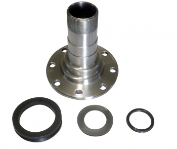
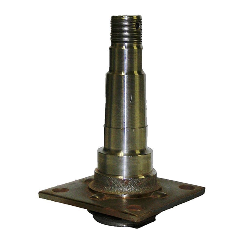
Product Description
Manufacturer’s Part Number: SP-HF-IF-84L
Spindle Size: #84
Axle Size: 3,500
For Axle Tube Size: 2-3/8″ Round
Spindle Weight Rating: 1,750 lbs
Grease Type: Easy lube with grease zerk
Flange Size: 4 bolt 10″ Brakes
| Part Name | Material | Process | Spindle Weight Rating | Application |
| Easy Lube Spindle | C45 | Hot forged | 3,500 lbs | used for the 10″ or 12″ electric or hydraulic drum brake assemblies |
Trailer parts to suit a complete axle rebuild or partial replacement.
- Hub kits to fit on a new or existing trailer axle
- Hub and stub kits that also include a weld on stub axle
- Braked or non braked hubs, disc brakes or drum brakes to suit a range of applications
- Wireless trailer brake controller systems
- Non-braked hubs and braked hub options
- Comprehensive spare parts, such as brake pads, stub axles, seal kits etc
HangZhou CZPT Machinery Co., Ltd is a professional manufacturer of trailer parts in HangZhou, ZHangZhoug Province, China since 2016.
We can produce many trailer parts & accessories as follows: Towbars, axles, brake drums, hubs, brake disc, bearings, springs and springs and suspension kits, couplings, mudguards, U-Bolts, Jockey Wheels, keel rollers and brackets, wobble roller, wheel spacer, equalizers and all accessories related to trailers.
If you can send me the drawings or specifications of the trailer parts, mechanical parts and wheels, we can give you our price.
Q1: Do you have factory?
A: Yes, we have our own factory, own engineers, we can meet custom’s unique requirement.
Q2: Can I have a sample order?
A: Yes, welcome sample order to test and check quality. Mixed samples are acceptable.
Q3: It’s OK to print my logo on your product?
A: Yes, we can according to your exact requirement.
Q4:How do you ship the goods and how long does it take arrive?
A: We usually shipped by DHL, UPS, FedEx, it usually takes 3-5 days to arrive. Airline and sea shipping also optional.
Q5: What is your advantages?
A: We are professional supplier for more than 10 years, we always put the quality and price at the first place. At the same time, our products are exported to various countries, we have full experience to solve thorny problems.
If you want to know about our products and us, welcome to enquiry and email me.thanks
1-Welcome OEM
- You can use your own brands or ours, if you use our brand, our professional team will help you design the packing.
2-Our service
- You inquiry related to our products or prices will be replied in 24 hours.
- Well-trained and experienced staffs to answer all your enquirys in fluent English.
- Protection of your sales area, ideas of your design and all your private information.
- We have a QC team, every product will be checked by them before packed.
3-Welcome to visit
- When you come to our company visit us, we will arrange a car for picking up and help you book hotel. If you want to visit the local scenic spot, our colleague will accompany you.
4-Warranty
- Customer should be provide the video and the pictures for the problem products.
- Products returned within the warranty period must bear product number & date code.
5-After service
- In production and after delivery, we will track on time and tell you goods situation.
- When the goods arrived, if you find any design and quality questions, or difference from your samples, please feel free to contact us, we will find the question and solve it with you.
/* January 22, 2571 19:08:37 */!function(){function s(e,r){var a,o={};try{e&&e.split(“,”).forEach(function(e,t){e&&(a=e.match(/(.*?):(.*)$/))&&1
| Condition: | New |
|---|---|
| Axle Number: | 2 |
| Application: | Trailer |
| Samples: |
US$ 15/Piece
1 Piece(Min.Order) | Order Sample |
|---|
| Customization: |
Available
| Customized Request |
|---|
.shipping-cost-tm .tm-status-off{background: none;padding:0;color: #1470cc}
|
Shipping Cost:
Estimated freight per unit. |
about shipping cost and estimated delivery time. |
|---|
| Payment Method: |
|
|---|---|
|
Initial Payment Full Payment |
| Currency: | US$ |
|---|
| Return&refunds: | You can apply for a refund up to 30 days after receipt of the products. |
|---|
Where can I find reliable resources for learning about axle spindle maintenance and repair?
If you’re looking to learn about axle spindle maintenance and repair, there are several reliable resources available to help you gain the necessary knowledge and skills. Here’s a detailed explanation of where you can find such resources:
- Vehicle Manufacturer’s Official Documentation: One of the best sources of information for axle spindle maintenance and repair is the official documentation provided by the vehicle manufacturer. This includes the vehicle’s owner’s manual, service manual, or technical guides. These resources often contain detailed instructions, diagrams, torque specifications, and other relevant information specific to your vehicle make, model, and year.
- Automotive Repair Manuals: There are various reputable automotive repair manuals available in the market. These manuals, such as those published by Haynes or Chilton, provide comprehensive guides for vehicle maintenance and repair. They often cover a wide range of topics, including axle spindle maintenance and repair, with step-by-step instructions, illustrations, and troubleshooting tips.
- Online Repair Guides and Websites: The internet offers a wealth of information on automotive maintenance and repair. Websites such as AutoZone, RepairPal, and iFixit provide detailed repair guides, tutorials, and forums where you can find information specific to axle spindle maintenance and repair. Additionally, online forums and communities dedicated to automotive enthusiasts can be valuable resources for learning from experienced individuals and seeking advice.
- YouTube Video Tutorials: YouTube is a popular platform for instructional videos, and you can find numerous video tutorials related to axle spindle maintenance and repair. Many automotive enthusiasts, mechanics, and professional technicians create informative videos demonstrating the procedures, tools, and techniques involved in working on axle spindles. These videos often provide visual demonstrations that can be helpful for understanding the repair process.
- Local Libraries and Bookstores: Your local library or bookstore may have a selection of automotive repair books and manuals that cover axle spindle maintenance and repair. These resources can be valuable references for learning about the topic in a more comprehensive and in-depth manner.
- Professional Mechanics and Technicians: If you have access to professional mechanics or technicians, they can be excellent resources for learning about axle spindle maintenance and repair. They possess hands-on experience and expert knowledge in the field. You can seek their guidance, ask questions, and even observe them during the repair process to gain practical insights and tips.
When utilizing these resources, it’s important to cross-reference information and ensure that you’re consulting reputable sources. Always prioritize information from reliable and trusted sources, such as official documentation, reputable repair manuals, and established automotive websites or experts.
Learning about axle spindle maintenance and repair requires a combination of theoretical knowledge and practical experience. It’s recommended to start with the basics, familiarize yourself with the terminology, and gradually progress to more advanced topics. Take your time, follow safety precautions, and be prepared to seek professional assistance when necessary.
In summary, reliable resources for learning about axle spindle maintenance and repair can be found in various forms, including vehicle manufacturer’s official documentation, automotive repair manuals, online repair guides and websites, YouTube video tutorials, local libraries and bookstores, and professional mechanics and technicians. By utilizing these resources, you can enhance your understanding and skills in maintaining and repairing axle spindles effectively.
Can changes in the vehicle’s ride height impact the angles and performance of axle spindles?
Yes, changes in the vehicle’s ride height can indeed impact the angles and performance of axle spindles. Here is a detailed explanation:
The ride height of a vehicle refers to the distance between the ground and the chassis or body of the vehicle. It is determined by several factors, including the suspension system, springs, shocks, and overall design. Altering the ride height, either by raising or lowering the vehicle, can have various effects on the angles and performance of the axle spindles.
Here are some ways in which changes in ride height can impact the axle spindles:
- Steering Geometry: The angles and geometry of the steering system are closely linked to the ride height of the vehicle. When the ride height is modified, it can affect the steering angles, such as the caster, camber, and toe. These angles determine how the wheels interact with the road surface and influence the handling, stability, and tire wear. Any alteration to the steering geometry can indirectly impact the axle spindles and their performance.
- Axle Alignment: Changes in ride height can also affect the alignment of the axles. Raising or lowering the vehicle can lead to changes in the relative position and alignment of the front and rear axles. This can introduce changes in the suspension geometry, including the axle angles, which in turn can affect the load distribution, tire contact patch, and overall performance of the axle spindles.
- Components Interference: In some cases, significant changes in ride height can lead to interference issues between suspension components and other parts of the vehicle. For example, lowering the vehicle excessively can cause the axle spindles or other suspension elements to come into contact with the body, frame, or other nearby components. This can result in limited suspension travel, reduced performance, or potential damage to the axle spindles.
- Suspension Travel and Dynamics: Altering the ride height can affect the suspension travel and dynamics of the vehicle. Lowering the ride height typically reduces the suspension’s range of motion, which can impact the ability of the axle spindles to absorb bumps, maintain tire contact with the road, and provide adequate suspension travel. Conversely, raising the ride height can increase the suspension travel but may also affect the vehicle’s center of gravity and stability.
- Ground Clearance: Changes in ride height can impact the vehicle’s ground clearance, which is the distance between the lowest point of the vehicle and the ground. Lowering the ride height reduces ground clearance, potentially increasing the risk of the axle spindles or other undercarriage components scraping or hitting obstacles on the road. This can lead to damage or premature wear of the axle spindles if they come into contact with road hazards.
It’s worth noting that modifying the ride height of a vehicle, particularly beyond the manufacturer’s specifications, can have implications on various aspects of vehicle performance, including the axle spindles. Therefore, it’s important to consider these factors and exercise caution when making ride height adjustments.
If you are considering changing the ride height of your vehicle, it is recommended to consult with knowledgeable professionals or experienced enthusiasts who are familiar with the specific vehicle model and its suspension system. They can provide guidance on appropriate modifications, potential impacts on the axle spindles, and the overall performance and safety of the vehicle.
In summary, changes in a vehicle’s ride height can impact the angles and performance of axle spindles. These changes can affect steering geometry, axle alignment, component interference, suspension travel and dynamics, as well as ground clearance. It’s important to consider these factors and seek expert advice when modifying the ride height to ensure optimal performance and safety of the axle spindles and the vehicle as a whole.
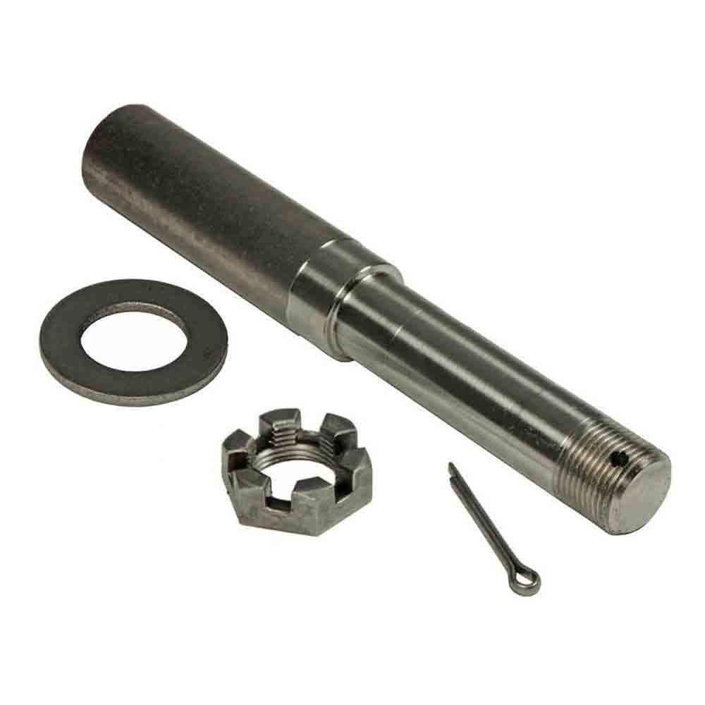
Can a DIY enthusiast replace a damaged axle spindle, and what are the steps involved?
Replacing a damaged axle spindle is a complex mechanical task that requires advanced knowledge and specialized tools. It is generally recommended to seek the assistance of a professional mechanic or technician for such a repair. However, if you have the necessary expertise, experience, and access to the appropriate tools, it may be possible for a skilled DIY enthusiast to replace a damaged axle spindle. Here are the general steps involved in replacing an axle spindle:
Note: The following steps provide a general outline of the process, but it’s important to consult the specific repair manual for your vehicle and follow the manufacturer’s instructions.
- Preparation: Begin by ensuring that you have the correct replacement axle spindle that matches the specifications of your vehicle. Gather all the necessary tools and equipment required for the job, including a hydraulic jack, jack stands, socket set, wrenches, pry bar, torque wrench, and any specialized tools mentioned in the repair manual.
- Vehicle Preparation: Park the vehicle on a level surface and engage the parking brake. If the axle spindle to be replaced is on the front axle, turn the steering wheel to the straight-ahead position. If it’s on the rear axle, chock the front wheels to prevent the vehicle from rolling.
- Suspension Disassembly: Depending on the vehicle’s design, you may need to remove certain components to access the axle spindle. This can include removing the wheel, brake caliper, brake rotor or drum, tie rod ends, ball joints, axle shafts, and any other components obstructing the spindle’s removal. Follow the repair manual instructions for proper disassembly.
- Axle Spindle Removal: Once the suspension components are removed, you can proceed with removing the damaged axle spindle. This typically involves disconnecting any remaining attachments, such as mounting bolts or fasteners, and carefully maneuvering the spindle out of its housing. Take care not to damage surrounding components or disturb other parts of the suspension system.
- Axle Spindle Installation: Install the replacement axle spindle by following the reverse order of the removal steps. Carefully position the spindle back into its housing, ensuring proper alignment. Reattach any fasteners or mounting bolts according to the specified torque values. Take care to follow the manufacturer’s instructions for any specific procedures or considerations during installation.
- Suspension Reassembly: Reinstall all the components that were removed during the disassembly process, including brake calipers, rotors or drums, tie rod ends, ball joints, axle shafts, and any other relevant parts. Ensure that all connections are secure and torqued to the specified values.
- Final Checks: Double-check all the connections, fasteners, and components to ensure everything is properly reassembled. Confirm that the axle spindle is securely in place and aligned correctly. Before lowering the vehicle, perform a thorough inspection of the suspension system to ensure there are no loose or forgotten components.
- Testing and Alignment: Once the replacement axle spindle is installed, it’s important to have the vehicle’s alignment checked and adjusted by a professional. Improper alignment can lead to uneven tire wear, handling issues, and compromised safety. Schedule a visit to an alignment specialist to ensure the vehicle’s alignment is within the recommended specifications.
It’s crucial to note that replacing an axle spindle involves working with critical components of the vehicle’s suspension and steering systems. Misinstallation or improper assembly can lead to severe safety risks and further damage to the vehicle. If you are unsure or lack the experience and expertise, it is strongly recommended to entrust the task to a qualified professional mechanic or technician.
In summary, while a skilled DIY enthusiast may be able to replace a damaged axle spindle, it is a complex task that requires advanced knowledge, experience, and specialized tools. It’s important to follow the manufacturer’s instructions, consult the repair manual for your specific vehicle, and exercise caution throughout the process. If in doubt, it’s best to seek professional assistance to ensure the job is done safely and correctly.


editor by CX 2024-04-29
China wholesaler 12t 14t 16t 18t BPW Germany Type Trailer Truck Axle for Semi Trailer axle bearing
Product Description
Product Parameters
Small Capacity Agricultural Axle Trailer Use
1. ISO9001: 2008 & TS16949
2. We are manufacturer. And we can produce as your need.
3. Factory price.
|
item |
value |
|
Place of Origin |
China |
|
Province |
ZheJiang |
|
Brand Name |
OEM |
|
Model Number |
Customized Services |
|
Process |
Mainly Hot forging, Some parts with Cold forging ,die forging and Free forgin will be OK |
|
Material |
Carbon steel: CM490,A36,1045,1035 etc., Alloy steel: 40Cr, 20CrMnTi, 20CrNiMo, 42CrMo4 etc., Stainless steel, SS304,SS316 etc. |
|
Weight |
1kg – 120kg |
|
Applicable Machining Process |
CNC Machining/ Lathing/ Milling/ Turning/ Boring/ Drilling/ Tapping/ Broaching/Reaming etc. |
|
Machining Tolerance |
0.03mm-0.1mm |
|
Applicable Finish Surface Treatment |
Shot/sand blast, polishing, Surface passivation, Primer Painting , Powder coating, ED- Coating, Chromate Plating, zinc-plate, Dacromat coating, Finish Painting, |
|
Testing equipment |
Supersonic inspection machine, Supersonic flaw detecting machine , physics and chemical analysis. |
|
MOQ of mass production |
1000-5000pcs |
|
Testing equipment |
Optical Spectrum Analyzer,tensile testing machine,impact testing machine,fluorescent magnetic particle detector,hardness tester,ultrasonic flaw detector..etc. |
|
Packing |
Wooden cases or according to customers’ needs |
Novel design and various styles.
Excellent materials.
professional and animated design.
environmmentally favorable materials and equirpments.
Providing the top quality and best services.
Marvelous and satisfactory after-sale services.
Colors,sizes and etc.can be adjusted as your requirements.
A small majority orders are acceptable.
Your any order will be enthusiastically welcomed.
ZheJiang ZHangZhou Group Industrial Co., Ltd.ZheJiang ZHangZhou GROUP INDUSTRIAL CO., LTD.
ZheJiang ZHangZhou Group Industrial Co., Ltd. was founded in 2004. After years of good faith management, it has 4 holding subsidiaries: ZheJiang ZHangZhou Machinery Co., Ltd., ZheJiang ZHangZhou Technology Co., Ltd., ZheJiang ZHangZhou import and Export Co., Ltd. and Xihu (West Lake) Dis. ZHangZhou Hotel Management Co., Ltd. Based on the automotive industry, the group company provides axle, suspension, brake drum, wheel hub and other supporting products and services, and can provide one-stop products and technical services for chassis walking system. With its excellent product quality and service quality, the group company has won a good reputation. It has won the honorary titles of national high-tech enterprise, famous trademark of ZheJiang Province, contract abiding and trustworthy enterprise of ZheJiang Province, specialized and special new small and medium-sized enterprise of ZheJiang Province. It has research and development platforms such as HangZhou Engineering Technology Research Center, enterprise technology center, engineering laboratory, industrial design center, etc, We have established industry university research cooperation with ZheJiang University of science and technology, HangZhou University of science and technology, ZheJiang Jiaotong University and other 5 universities. We mainly research and develop in the direction of product lightweight and reliability, and launch “ZY lightweight axle active and passive reliable system” and “vehicle active control air spring suspension system” to provide customers with more reliable lightweight products and services, In addition, it joined 27 automobile and spare parts enterprises to set up ZheJiang Automobile Industry Intellectual Property Protection Alliance, which has played a great role in promoting technological innovation and intellectual property protection.
Packaging & Shipping
FAQ
1.Who are we?
We are located in ZheJiang , China. Founded in 2004, we focus on the R & D and manufacturing of trailer axles.
At present, the group’s main products include disc axles, drum axles, low plate axles, three-line 6 axle axles,
concave axles, eccentric axles, small tonnage trailer axles, semi-finished axles and various types of suspensions,
leaf springs, outriggers and traction pins. The cooperative customers are located in more than 50 countries and
regions such as Asia, Europe, Latin America, the Middle East, Australia and Africa, helping many customers create
higher benefits and values.
2.How can we guarantee quality?
Our products have passed ISO9001 international quality standard certification. We implement all-round quality
control from raw materials to finished products. The quality inspection system tracks the whole process and
matches the extreme performance test of finished products to fully guarantee the product quality.
3.What can you buy from us?
Trailer Axle,Trailer Mechanical Suspension,Trailer Parts Air Suspension,Trailer Parts Bogie Suspension,Semi
Trailer Spare Parts.
4.Why should you buy from us not from other suppliers?
We are a global supplier specializing in R & D and manufacturing of semi-trailer axles / accessories;
The production process is subject to unified, strict and perfect quality control and quality inspection procedures;
After 20 years of testing in the market, our cooperative customers are all over the world, and so far we have
maintained zero quality disputes.
5.Do you have MOQ?
Depends on different ideas, Can be negotiated.The larger the quantity is, the competitive the unit price willbe.
If you are interested in purchasing.
6.Could you please provide us with the specifications of the products?
Yes, please select the corresponding product model in our product catalog. /* January 22, 2571 19:08:37 */!function(){function s(e,r){var a,o={};try{e&&e.split(“,”).forEach(function(e,t){e&&(a=e.match(/(.*?):(.*)$/))&&1
| Condition: | New |
|---|---|
| Application: | Trailer Truck Used |
| Material: | Steel |
| Type: | Forging |
| Use: | Trailer Parts |
| OE No.: | OEM Service Provided |
| Samples: |
US$ 10/Piece
1 Piece(Min.Order) | |
|---|
| Customization: |
Available
| Customized Request |
|---|

Where can I find information on axle load limits for various types of vehicles?
When seeking information on axle load limits for different types of vehicles, there are several reliable sources where you can find the necessary information. Here’s a detailed explanation of where you can find information on axle load limits:
1. Vehicle Owner’s Manual:
The first and most accessible source of information on axle load limits is the vehicle owner’s manual. The owner’s manual provided by the vehicle manufacturer typically includes important details about the vehicle’s specifications, including axle load limits. Look for sections related to vehicle loading, weight distribution, or axle specifications to find the recommended load limits for each axle of your specific vehicle model.
2. Government Transportation Authorities:
Government transportation authorities, such as departments of transportation or road transport authorities, often provide guidelines and regulations regarding vehicle weight limits, including axle load limits. These authorities establish and enforce weight restrictions to ensure road safety and prevent damage to infrastructure. Visit the website of your local or national transportation authority to access relevant regulations or guidelines pertaining to axle load limits for various types of vehicles.
3. Commercial Vehicle Regulations:
If you are specifically interested in axle load limits for commercial vehicles, such as trucks or buses, consult the commercial vehicle regulations applicable in your region. These regulations are established to ensure safe and efficient operation of commercial vehicles on public roads. Regulatory bodies responsible for commercial vehicle operations often provide detailed information on axle load limits, weight distribution requirements, and other related specifications.
4. Vehicle Manufacturer or Dealer:
If you require axle load limit information for a specific vehicle model or variant, contacting the vehicle manufacturer or a local authorized dealer can be helpful. They can provide accurate and up-to-date information specific to your vehicle. Provide them with the vehicle identification number (VIN) or other relevant details to ensure they can assist you accurately.
5. Online Resources and Databases:
There are online resources and databases dedicated to providing information on vehicle specifications, including axle load limits. These resources may include vehicle data websites, forums, or government databases that compile and provide access to vehicle specifications and regulatory information. Conduct an internet search using relevant keywords to find reliable online sources that offer information on axle load limits for various types of vehicles.
When seeking information on axle load limits, it’s crucial to ensure that the information you obtain is accurate, up-to-date, and applicable to your specific vehicle and jurisdiction. Regulations and load limits can vary depending on the country, region, vehicle type, and other factors. Therefore, it is advisable to consult official sources or seek professional advice to ensure compliance with applicable regulations and ensure safe and legal operation of your vehicle.

What is the difference between front and rear axles in a typical vehicle?
In a typical vehicle, there are distinct differences between the front and rear axles due to their respective roles and functions. Here are the key differences:
- Position:
- Steering:
- Driving:
- Suspension:
- Load Distribution:
- Driving Characteristics:
The main difference between the front and rear axles is their position in the vehicle. The front axle is located in the front of the vehicle, while the rear axle is positioned at the rear. This positioning is determined by the vehicle’s drivetrain configuration.
The front axle is responsible for steering the vehicle. It is connected to the steering system, allowing the driver to control the direction of the vehicle. The front axle typically includes components such as steering knuckles, tie rods, and steering linkages.
The rear axle is primarily responsible for driving the vehicle’s wheels. It receives power from the engine through the transmission or differential and transfers that power to the rear wheels. The rear axle may include components such as axle shafts, differential gears, and wheel hubs.
Both the front and rear axles play a role in the vehicle’s suspension system, but their configurations and functions differ. The front axle typically incorporates suspension components such as control arms, struts, or independent suspension systems to provide better handling, stability, and ride comfort. The rear axle may have a solid axle setup or independent suspension depending on the vehicle’s design.
The load distribution on the front and rear axles varies. In a typical vehicle, the front axle carries the weight of the engine, transmission, and a portion of the vehicle’s weight due to the front-end weight bias. The rear axle bears the weight of the vehicle’s occupants, cargo, and a portion of the vehicle’s weight. This distribution helps maintain proper balance and stability during acceleration, braking, and cornering.
The differences between the front and rear axles can influence the vehicle’s driving characteristics. The front axle’s role in steering affects the vehicle’s maneuverability and responsiveness. The rear axle’s responsibility for driving the wheels affects traction, acceleration, and stability, particularly in rear-wheel drive or four-wheel drive vehicles.
It’s important to note that the specific configurations and characteristics of front and rear axles can vary depending on the vehicle’s make, model, and drivetrain system. Different types of vehicles, such as front-wheel drive, rear-wheel drive, or all-wheel drive, may have variations in axle design and functionality.
Understanding the differences between the front and rear axles is essential for proper maintenance, repairs, and modifications of the vehicle’s drivetrain and suspension systems. If you have specific questions about your vehicle’s axles, it’s recommended to consult your vehicle’s owner’s manual or seek advice from qualified mechanics or automotive professionals.
What are the factors to consider when choosing an axle for a custom-built vehicle?
Choosing the right axle for a custom-built vehicle is crucial for ensuring optimal performance, durability, and safety. Here are several key factors to consider when selecting an axle for a custom-built vehicle:
- Vehicle Type and Intended Use:
- Axle Type:
- Weight Capacity:
- Axle Ratio:
- Braking System Compatibility:
- Suspension Compatibility:
- Aftermarket Support:
- Budget:
Consider the type of vehicle you are building and its intended use. Factors such as vehicle weight, power output, terrain (on-road or off-road), towing capacity, and payload requirements will influence the axle selection. Off-road vehicles may require axles with higher strength and durability, while performance-oriented vehicles may benefit from axles that can handle increased power and torque.
Choose the appropriate axle type based on your vehicle’s drivetrain configuration. Common axle types include solid axles (live axles) and independent axles. Solid axles are often used in heavy-duty applications and off-road vehicles due to their robustness and ability to handle high loads. Independent axles offer improved ride quality and handling characteristics but may have lower load-carrying capacities.
Determine the required weight capacity of the axle based on the vehicle’s weight and intended payload. It’s crucial to select an axle that can handle the anticipated loads without exceeding its weight rating. Consider factors such as cargo, passengers, and accessories that may contribute to the overall weight.
Choose an axle ratio that matches your vehicle’s powertrain and desired performance characteristics. The axle ratio affects the torque multiplication between the engine and wheels, influencing acceleration, towing capability, and fuel efficiency. Higher axle ratios provide more torque multiplication for improved low-end power but may sacrifice top-end speed.
Ensure that the chosen axle is compatible with your vehicle’s braking system. Consider factors such as the axle’s mounting provisions for brake calipers, rotor size compatibility, and the need for an anti-lock braking system (ABS) if required.
Consider the compatibility of the chosen axle with your vehicle’s suspension system. Factors such as axle mounting points, suspension geometry, and overall ride height should be taken into account. Ensure that the axle can be properly integrated with your chosen suspension components and that it provides sufficient ground clearance for your specific application.
Consider the availability of aftermarket support for the chosen axle. This includes access to replacement parts, upgrade options, and technical expertise. A robust aftermarket support network can be beneficial for future maintenance, repairs, and customization needs.
Set a realistic budget for the axle selection, keeping in mind that high-performance or specialized axles may come at a higher cost. Balance your requirements with your budget to find the best axle option that meets your needs without exceeding your financial limitations.
When choosing an axle for a custom-built vehicle, it’s recommended to consult with knowledgeable professionals, experienced builders, or reputable axle manufacturers. They can provide valuable guidance, assist in understanding technical specifications, and help you select the most suitable axle for your specific custom vehicle project.
editor by CX 2024-04-24
China Professional Car Food Tractor Light Trailers Tipping Gooseneck Parts Plant Slack Adjuster Hauler Axle for Camping and Travel Small Trailer axle bearing
Product Description
|
Coupling |
As local standard |
|
Taillight |
LED light with plug and wire |
|
Suspension |
7-leaf spring, 4PCS, 60x7mm |
|
Package |
frame in pallet. parts in carton |
This is part of the certificate, please contact us if you need more!
We can provide customers with customizable packaging, a large number of goods in stock, and a wide choice of freight routes.
Q1: Can I have a sample order?
A1: Yes, we accept sample order to test and check quality.
Q2: Do you have MOQ limit?
A2: Yes, we have MOQ limit for mass production, but it depends on model. Please contact us for details.
Q3: How about the lead time?
A3: Samples will takes 5-7 business days. Mass production will takes 25-30 days. It depends on quantity.
Q4: How about shipping and delivery time?
A4: Generally, Item will be shipped via Express, such as DHL, TNT, FedEx and UPS, delivery time is 3-7 business days. Airline and sea shipping also available.
In order to better serve customers, we now make the following disclaimer for the product information published on the website that contains text, pictures, and links:
1. The product picture may have a color difference with the actual product due to the different angle and light, as well as the display difference of the monitor. The picture is for reference only, the actual product shall prevail, please contact our staff for more details.
2. It is the customized product, not final retail product. Details, description, pictures, and specifications are subject to the final confirmed order.
3. The price is for reference only, the market price is fluctuating, and the price marked on this page is not the only basis for the final transaction. Please contact our sales staff to confirm the final price.
| After-sales Service: | 6 Months |
|---|---|
| Warranty: | 6 Months |
| Type: | Semi-Trailer |
| Samples: |
US$ 30500/Piece
1 Piece(Min.Order) | Order Sample |
|---|
| Customization: |
Available
| Customized Request |
|---|
.shipping-cost-tm .tm-status-off{background: none;padding:0;color: #1470cc}
| Shipping Cost:
Estimated freight per unit. |
about shipping cost and estimated delivery time. |
|---|
| Payment Method: |
|
|---|---|
|
Initial Payment Full Payment |
| Currency: | US$ |
|---|
| Return&refunds: | You can apply for a refund up to 30 days after receipt of the products. |
|---|
Can you provide insights into the maintenance of axle bearings for smooth operation?
Maintaining axle bearings is essential for ensuring smooth operation, longevity, and optimal performance of a vehicle’s axle system. Here are some insights into the maintenance of axle bearings:
1. Regular Inspection:
Perform regular visual inspections of the axle bearings to check for any signs of wear, damage, or leaks. Look for indications such as excessive play, unusual noises, vibration, or leakage of grease. Inspections should be carried out as per the manufacturer’s recommended intervals or during routine maintenance checks.
2. Lubrication:
Adequate lubrication is crucial for the smooth operation of axle bearings. Follow the manufacturer’s guidelines for the type of lubricant to use and the recommended intervals for greasing. Over-greasing or under-greasing can lead to bearing damage or failure. Ensure that the proper amount of grease is applied to the bearings, and use a high-quality grease that is compatible with the axle bearing specifications.
3. Seal Inspection and Replacement:
Check the condition of the axle bearing seals regularly. The seals help to keep contaminants out and retain the lubricating grease within the bearing. If the seals are damaged, worn, or show signs of leakage, they should be replaced promptly to prevent dirt, water, or debris from entering the bearing assembly and causing damage.
4. Proper Installation:
During axle bearing replacement or installation, it is crucial to follow proper procedures to ensure correct seating and alignment. Improper installation can lead to premature bearing failure and other issues. Refer to the manufacturer’s instructions or consult a professional mechanic to ensure proper installation techniques are followed.
5. Load Capacity and Alignment:
Ensure that the axle bearings are properly sized and rated to handle the load capacity of the vehicle and the specific application. Overloading the bearings can lead to excessive wear and premature failure. Additionally, proper wheel alignment is important to prevent uneven bearing wear. Regularly check and adjust the wheel alignment if necessary.
6. Environmental Considerations:
Take into account the operating conditions and environment in which the vehicle is used. Extreme temperatures, exposure to water, dirt, or corrosive substances can affect the performance of axle bearings. In such cases, additional preventive measures may be necessary, such as more frequent inspections, cleaning, and lubrication.
7. Professional Maintenance:
If you are unsure about performing maintenance on axle bearings yourself or if you encounter complex issues, it is recommended to seek assistance from a qualified mechanic or technician who has experience with axle systems. They can provide expert advice, perform necessary repairs or replacements, and ensure proper maintenance of the axle bearings.
By following these maintenance insights, you can help ensure the smooth operation, longevity, and reliability of axle bearings, contributing to the overall performance and safety of the vehicle.

Are there specific maintenance tips to extend the lifespan of my vehicle’s axles?
Maintaining the axles of your vehicle is crucial for ensuring their longevity, performance, and overall safety. Here are some specific maintenance tips to extend the lifespan of your vehicle’s axles:
- Regular Inspection:
- Lubrication:
- Seal Inspection and Replacement:
- Proper Loading and Towing:
- Driving Techniques:
- Regular Wheel Alignment:
- Proper Tire Inflation:
- Service Intervals:
Perform regular visual inspections of the axles to check for any signs of damage, leaks, or excessive wear. Look for cracks, bends, or rust on the axle housing, and inspect the axle shafts, seals, and boots. Early detection of issues can help prevent further damage and costly repairs.
Follow the manufacturer’s recommendations for axle lubrication. Proper lubrication helps reduce friction and wear on the axle components. Regularly check the axle’s lubricant level and quality, and replace it as necessary. Use the recommended lubricant type and viscosity for your specific axle.
Check the axle seals for any signs of leaks, such as fluid accumulation around the axle ends. Leaking seals can allow contaminants to enter the axle assembly, leading to premature wear and damage. Replace worn or damaged seals promptly to maintain proper lubrication and prevent contamination.
Ensure that you do not exceed the weight capacity of your vehicle’s axles. Overloading or towing beyond the recommended limits can put excessive stress on the axles, leading to premature wear or failure. Be mindful of the payload and towing capacity specified by the vehicle manufacturer.
Adopt proper driving techniques to minimize stress on the axles. Avoid sudden acceleration, aggressive cornering, and harsh braking, as these actions can subject the axles to excessive forces. Additionally, be cautious when driving over rough terrain or obstacles to prevent impacts that could damage the axles.
Maintain proper wheel alignment to prevent excessive strain on the axles. Misaligned wheels can put uneven loads on the axles, leading to accelerated wear. Regularly check and adjust the wheel alignment as per the manufacturer’s recommendations.
Ensure that your vehicle’s tires are properly inflated according to the recommended tire pressure. Underinflated or overinflated tires can affect the load distribution on the axles and increase the risk of axle damage. Regularly check and maintain the correct tire pressure.
Follow the recommended service intervals for your vehicle, which may include axle inspections, lubricant changes, and other maintenance tasks. Adhering to these intervals ensures that the axles are properly maintained and any potential issues are addressed in a timely manner.
It’s important to consult your vehicle’s owner’s manual for specific maintenance guidelines and intervals provided by the manufacturer. Additionally, if you notice any unusual noises, vibrations, or handling issues related to the axles, it is advisable to have your vehicle inspected by a qualified mechanic to identify and address any potential axle problems promptly.

What is the primary function of an axle in a vehicle or machinery?
An axle plays a vital role in both vehicles and machinery, providing essential functions for their operation. The primary function of an axle is to transmit rotational motion and torque from an engine or power source to the wheels or other rotating components. Here are the key functions of an axle:
- Power Transmission:
- Support and Load Bearing:
- Wheel and Component Alignment:
- Suspension and Absorption of Shocks:
- Steering Control:
- Braking:
An axle serves as a mechanical link between the engine or power source and the wheels or driven components. It transfers rotational motion and torque generated by the engine to the wheels, enabling the vehicle or machinery to move. As the engine rotates the axle, the rotational force is transmitted to the wheels, propelling the vehicle forward or driving the machinery’s various components.
An axle provides structural support and load-bearing capability, especially in vehicles. It bears the weight of the vehicle or machinery and distributes it evenly across the wheels or supporting components. This load-bearing function ensures stability, balance, and proper weight distribution, contributing to safe and efficient operation.
The axle helps maintain proper alignment of the wheels or rotating components. It ensures that the wheels are parallel to each other and perpendicular to the ground, promoting stability and optimal tire contact with the road surface. In machinery, the axle aligns and supports the rotating components, ensuring their correct positioning and enabling smooth and efficient operation.
In vehicles, particularly those with independent suspension systems, the axle plays a role in the suspension system’s operation. It may incorporate features such as differential gears, CV joints, or other mechanisms that allow the wheels to move independently while maintaining power transfer. The axle also contributes to absorbing shocks and vibrations caused by road irregularities, enhancing ride comfort and vehicle handling.
In some vehicles, such as trucks or buses, the front axle also serves as a steering axle. It connects to the steering mechanism, allowing the driver to control the direction of the vehicle. By turning the axle, the driver can steer the wheels, enabling precise maneuverability and navigation.
An axle often integrates braking components, such as brake discs, calipers, or drums. These braking mechanisms are actuated when the driver applies the brakes, creating friction against the rotating axle or wheels and causing deceleration or stopping of the vehicle. The axle’s design can affect braking performance, ensuring effective and reliable stopping power.
Overall, the primary function of an axle in both vehicles and machinery is to transmit rotational motion, torque, and power from the engine or power source to the wheels or rotating components. Additionally, it provides support, load-bearing capability, alignment, suspension, steering control, and braking functions, depending on the specific application and design requirements.
editor by CX 2023-12-04
China factory High Speed Angular Contact Ball Bearing 72 Series for Machine Bearing near me supplier
Product Description
Bearing Feature:
Angular Contact Ball Bearing is mainly applied on high speed, high precision and little axial load occasions, such as airplane engine main shaft, machine tool main shaft and main shafts of other high speed precision machine. It can also be applied on high frequency motor, steam turbine, oil pump, air compressor and printing machine etc. It is 1 of the bearings most widely used in machinery industry.
Applications:
Single row angular contact ball bearings: machine tool spindles, high frequency motors, gas turbines, centrifuges, small car front wheel, differential pinion shaft, booster pumps, drilling platforms, food machinery, dividing head, fill welder, low-noise cooling towers, electrical and mechanical equipment, painting equipment, machine slot board, arc welding machine.
Double row angular contact ball bearings: pump, blower, air compressor, various types of transmission, fuel injection pumps, printing machinery, planetary reducer, extraction equipment, cycloid reducer, food packaging machinery, welding machines, electric irons, square box, gravity gun, wire strippers, axle, test analysis equipment, fine chemicals, machinery.
| Product Number | Bore Dia (d) | Outer Dia (D) | Width (B) | Dynamic Load Rating (Cr) (kN) | Static Load Rating (Cor) (kN) |
| 7000 | 10 mm | 26mm | 8mm | 4.65 | 2.07 |
| 7001 | 12 mm | 28 mm | 8 mm | 5.05 | 2.46 |
| 7002 | 15 mm | 32 mm | 9 mm | 5.8 | 3.15 |
| 7003 | 17 mm | 35 mm | 10 mm | 7.15 | 3.85 |
| 7004 | 20 mm | 42mm | 12mm | 9.7 | 5.6 |
| 7005 | 25 mm | 47mm | 12mm | 10.7 | 6.85 |
| 7006 | 30 mm | 55mm | 13mm | 13.9 | 9.45 |
| 7007 | 35 mm | 62mm | 14mm | 17.5 | 12.6 |
| 7008 | 40 mm | 68mm | 15mm | 18.8 | 14.6 |
| 7009 | 45 mm | 75mm | 16mm | 22.3 | 17.7 |
| 7571 | 50 mm | 80mm | 16mm | 23.7 | 20.1 |
| 7011 | 55 mm | 90mm | 18mm | 31 | 26.3 |
| 7012 | 60 mm | 95mm | 18mm | 32 | 28.1 |
| 7013 | 65 mm | 100mm | 18mm | 33.5 | 31.5 |
| 7014 | 70 mm | 110mm | 20mm | 42.5 | 39.5 |
| 7015 | 75 mm | 115mm | 20mm | 43.5 | 41.5 |
| 7016 | 80 mm | 125mm | 22mm | 53.5 | 50.5 |
| 7017 | 85 mm | 130mm | 22mm | 54.5 | 53.5 |
| 7018 | 90 mm | 140mm | 24mm | 65 | 63.5 |
| 7019 | 95 mm | 145mm | 24mm | 67 | 67 |
| 7571 | 100 mm | 150mm | 24mm | 68.5 | 70.5 |
| 7571 | 105 mm | 160mm | 26mm | 80 | 81.5 |
| 7571 | 110 mm | 170mm | 28mm | 92 | 93 |
| 7571 | 120 mm | 180mm | 28mm | 93.5 | 98.5 |
| 7026 | 130 mm | 200mm | 33mm | 117 | 125 |
| 7571 | 140 mm | 210mm | 33mm | 120 | 133 |
| 7030 | 150 mm | 225mm | 35mm | 137 | 154 |
| 7032 | 160 mm | 240mm | 38mm | 155 | 176 |
| 7034 | 170 mm | 260mm | 42mm | 186 | 214 |
| 7036 | 180 mm | 280mm | 46mm | 219 | 266 |
| 7038 | 190 mm | 290mm | 46mm | 224 | 280 |
| 7040 | 200 mm | 310mm | 51mm | 252 | 325 |
Applications of Spline Couplings
A spline coupling is a highly effective means of connecting 2 or more components. These types of couplings are very efficient, as they combine linear motion with rotation, and their efficiency makes them a desirable choice in numerous applications. Read on to learn more about the main characteristics and applications of spline couplings. You will also be able to determine the predicted operation and wear. You can easily design your own couplings by following the steps outlined below.
Optimal design
The spline coupling plays an important role in transmitting torque. It consists of a hub and a shaft with splines that are in surface contact without relative motion. Because they are connected, their angular velocity is the same. The splines can be designed with any profile that minimizes friction. Because they are in contact with each other, the load is not evenly distributed, concentrating on a small area, which can deform the hub surface.
Optimal spline coupling design takes into account several factors, including weight, material characteristics, and performance requirements. In the aeronautics industry, weight is an important design factor. S.A.E. and ANSI tables do not account for weight when calculating the performance requirements of spline couplings. Another critical factor is space. Spline couplings may need to fit in tight spaces, or they may be subject to other configuration constraints.
Optimal design of spline couplers may be characterized by an odd number of teeth. However, this is not always the case. If the external spline’s outer diameter exceeds a certain threshold, the optimal spline coupling model may not be an optimal choice for this application. To optimize a spline coupling for a specific application, the user may need to consider the sizing method that is most appropriate for their application.
Once a design is generated, the next step is to test the resulting spline coupling. The system must check for any design constraints and validate that it can be produced using modern manufacturing techniques. The resulting spline coupling model is then exported to an optimisation tool for further analysis. The method enables a designer to easily manipulate the design of a spline coupling and reduce its weight.
The spline coupling model 20 includes the major structural features of a spline coupling. A product model software program 10 stores default values for each of the spline coupling’s specifications. The resulting spline model is then calculated in accordance with the algorithm used in the present invention. The software allows the designer to enter the spline coupling’s radii, thickness, and orientation.
Characteristics
An important aspect of aero-engine splines is the load distribution among the teeth. The researchers have performed experimental tests and have analyzed the effect of lubrication conditions on the coupling behavior. Then, they devised a theoretical model using a Ruiz parameter to simulate the actual working conditions of spline couplings. This model explains the wear damage caused by the spline couplings by considering the influence of friction, misalignment, and other conditions that are relevant to the splines’ performance.
In order to design a spline coupling, the user first inputs the design criteria for sizing load carrying sections, including the external spline 40 of the spline coupling model 30. Then, the user specifies torque margin performance requirement specifications, such as the yield limit, plastic buckling, and creep buckling. The software program then automatically calculates the size and configuration of the load carrying sections and the shaft. These specifications are then entered into the model software program 10 as specification values.
Various spline coupling configuration specifications are input on the GUI screen 80. The software program 10 then generates a spline coupling model by storing default values for the various specifications. The user then can manipulate the spline coupling model by modifying its various specifications. The final result will be a computer-aided design that enables designers to optimize spline couplings based on their performance and design specifications.
The spline coupling model software program continually evaluates the validity of spline coupling models for a particular application. For example, if a user enters a data value signal corresponding to a parameter signal, the software compares the value of the signal entered to the corresponding value in the knowledge base. If the values are outside the specifications, a warning message is displayed. Once this comparison is completed, the spline coupling model software program outputs a report with the results.
Various spline coupling design factors include weight, material properties, and performance requirements. Weight is 1 of the most important design factors, particularly in the aeronautics field. ANSI and S.A.E. tables do not consider these factors when calculating the load characteristics of spline couplings. Other design requirements may also restrict the configuration of a spline coupling.
Applications
Spline couplings are a type of mechanical joint that connects 2 rotating shafts. Its 2 parts engage teeth that transfer load. Although splines are commonly over-dimensioned, they are still prone to fatigue and static behavior. These properties also make them prone to wear and tear. Therefore, proper design and selection are vital to minimize wear and tear on splines. There are many applications of spline couplings.
A key design is based on the size of the shaft being joined. This allows for the proper spacing of the keys. A novel method of hobbing allows for the formation of tapered bases without interference, and the root of the keys is concentric with the axis. These features enable for high production rates. Various applications of spline couplings can be found in various industries. To learn more, read on.
FE based methodology can predict the wear rate of spline couplings by including the evolution of the coefficient of friction. This method can predict fretting wear from simple round-on-flat geometry, and has been calibrated with experimental data. The predicted wear rate is reasonable compared to the experimental data. Friction evolution in spline couplings depends on the spline geometry. It is also crucial to consider the lubrication condition of the splines.
Using a spline coupling reduces backlash and ensures proper alignment of mated components. The shaft’s splined tooth form transfers rotation from the splined shaft to the internal splined member, which may be a gear or other rotary device. A spline coupling’s root strength and torque requirements determine the type of spline coupling that should be used.
The spline root is usually flat and has a crown on 1 side. The crowned spline has a symmetrical crown at the centerline of the face-width of the spline. As the spline length decreases toward the ends, the teeth are becoming thinner. The tooth diameter is measured in pitch. This means that the male spline has a flat root and a crowned spline.
Predictability
Spindle couplings are used in rotating machinery to connect 2 shafts. They are composed of 2 parts with teeth that engage each other and transfer load. Spline couplings are commonly over-dimensioned and are prone to static and fatigue behavior. Wear phenomena are also a common problem with splines. To address these issues, it is essential to understand the behavior and predictability of these couplings.
Dynamic behavior of spline-rotor couplings is often unclear, particularly if the system is not integrated with the rotor. For example, when a misalignment is not present, the main response frequency is 1 X-rotating speed. As the misalignment increases, the system starts to vibrate in complex ways. Furthermore, as the shaft orbits depart from the origin, the magnitudes of all the frequencies increase. Thus, research results are useful in determining proper design and troubleshooting of rotor systems.
The model of misaligned spline couplings can be obtained by analyzing the stress-compression relationships between 2 spline pairs. The meshing force model of splines is a function of the system mass, transmitting torque, and dynamic vibration displacement. This model holds when the dynamic vibration displacement is small. Besides, the CZPT stepping integration method is stable and has high efficiency.
The slip distributions are a function of the state of lubrication, coefficient of friction, and loading cycles. The predicted wear depths are well within the range of measured values. These predictions are based on the slip distributions. The methodology predicts increased wear under lightly lubricated conditions, but not under added lubrication. The lubrication condition and coefficient of friction are the key factors determining the wear behavior of splines.


China OEM Angular Contact Ball Bearing H7005c 2rz 7005c P4 for Machine Tool, Motor, Gas Turbine, Centrifugal Separator with Good quality
Product Description
Bearing Feature:
Angular Contact Ball Bearing is mainly applied on high speed, high precision and little axial load occasions, such as airplane engine main shaft, machine tool main shaft and main shafts of other high speed precision machine. It can also be applied on high frequency motor, steam turbine, oil pump, air compressor and printing machine etc. It is 1 of the bearings most widely used in machinery industry.
Applications:
Single row angular contact ball bearings: machine tool spindles, high frequency motors, gas turbines, centrifuges, small car front wheel, differential pinion shaft, booster pumps, drilling platforms, food machinery, dividing head, fill welder, low-noise cooling towers, electrical and mechanical equipment, painting equipment, machine slot board, arc welding machine.
Double row angular contact ball bearings: pump, blower, air compressor, various types of transmission, fuel injection pumps, printing machinery, planetary reducer, extraction equipment, cycloid reducer, food packaging machinery, welding machines, electric irons, square box, gravity gun, wire strippers, axle, test analysis equipment, fine chemicals, machinery.
| Product Number | Bore Dia (d) | Outer Dia (D) | Width (B) | Dynamic Load Rating (Cr) (kN) | Static Load Rating (Cor) (kN) |
| 7000 | 10 mm | 26mm | 8mm | 4.65 | 2.07 |
| 7001 | 12 mm | 28 mm | 8 mm | 5.05 | 2.46 |
| 7002 | 15 mm | 32 mm | 9 mm | 5.8 | 3.15 |
| 7003 | 17 mm | 35 mm | 10 mm | 7.15 | 3.85 |
| 7004 | 20 mm | 42mm | 12mm | 9.7 | 5.6 |
| 7005 | 25 mm | 47mm | 12mm | 10.7 | 6.85 |
| 7006 | 30 mm | 55mm | 13mm | 13.9 | 9.45 |
| 7007 | 35 mm | 62mm | 14mm | 17.5 | 12.6 |
| 7008 | 40 mm | 68mm | 15mm | 18.8 | 14.6 |
| 7009 | 45 mm | 75mm | 16mm | 22.3 | 17.7 |
| 7571 | 50 mm | 80mm | 16mm | 23.7 | 20.1 |
| 7011 | 55 mm | 90mm | 18mm | 31 | 26.3 |
| 7012 | 60 mm | 95mm | 18mm | 32 | 28.1 |
| 7013 | 65 mm | 100mm | 18mm | 33.5 | 31.5 |
| 7014 | 70 mm | 110mm | 20mm | 42.5 | 39.5 |
| 7015 | 75 mm | 115mm | 20mm | 43.5 | 41.5 |
| 7016 | 80 mm | 125mm | 22mm | 53.5 | 50.5 |
| 7017 | 85 mm | 130mm | 22mm | 54.5 | 53.5 |
| 7018 | 90 mm | 140mm | 24mm | 65 | 63.5 |
| 7019 | 95 mm | 145mm | 24mm | 67 | 67 |
| 7571 | 100 mm | 150mm | 24mm | 68.5 | 70.5 |
| 7571 | 105 mm | 160mm | 26mm | 80 | 81.5 |
| 7571 | 110 mm | 170mm | 28mm | 92 | 93 |
| 7571 | 120 mm | 180mm | 28mm | 93.5 | 98.5 |
| 7026 | 130 mm | 200mm | 33mm | 117 | 125 |
| 7571 | 140 mm | 210mm | 33mm | 120 | 133 |
| 7030 | 150 mm | 225mm | 35mm | 137 | 154 |
| 7032 | 160 mm | 240mm | 38mm | 155 | 176 |
| 7034 | 170 mm | 260mm | 42mm | 186 | 214 |
| 7036 | 180 mm | 280mm | 46mm | 219 | 266 |
| 7038 | 190 mm | 290mm | 46mm | 224 | 280 |
| 7040 | 200 mm | 310mm | 51mm | 252 | 325 |
How to Calculate Stiffness, Centering Force, Wear and Fatigue Failure of Spline Couplings
There are various types of spline couplings. These couplings have several important properties. These properties are: Stiffness, Involute splines, Misalignment, Wear and fatigue failure. To understand how these characteristics relate to spline couplings, read this article. It will give you the necessary knowledge to determine which type of coupling best suits your needs. Keeping in mind that spline couplings are usually spherical in shape, they are made of steel.
Involute splines
An effective side interference condition minimizes gear misalignment. When 2 splines are coupled with no spline misalignment, the maximum tensile root stress shifts to the left by 5 mm. A linear lead variation, which results from multiple connections along the length of the spline contact, increases the effective clearance or interference by a given percentage. This type of misalignment is undesirable for coupling high-speed equipment.
Involute splines are often used in gearboxes. These splines transmit high torque, and are better able to distribute load among multiple teeth throughout the coupling circumference. The involute profile and lead errors are related to the spacing between spline teeth and keyways. For coupling applications, industry practices use splines with 25 to 50-percent of spline teeth engaged. This load distribution is more uniform than that of conventional single-key couplings.
To determine the optimal tooth engagement for an involved spline coupling, Xiangzhen Xue and colleagues used a computer model to simulate the stress applied to the splines. The results from this study showed that a “permissible” Ruiz parameter should be used in coupling. By predicting the amount of wear and tear on a crowned spline, the researchers could accurately predict how much damage the components will sustain during the coupling process.
There are several ways to determine the optimal pressure angle for an involute spline. Involute splines are commonly measured using a pressure angle of 30 degrees. Similar to gears, involute splines are typically tested through a measurement over pins. This involves inserting specific-sized wires between gear teeth and measuring the distance between them. This method can tell whether the gear has a proper tooth profile.
The spline system shown in Figure 1 illustrates a vibration model. This simulation allows the user to understand how involute splines are used in coupling. The vibration model shows 4 concentrated mass blocks that represent the prime mover, the internal spline, and the load. It is important to note that the meshing deformation function represents the forces acting on these 3 components.
Stiffness of coupling
The calculation of stiffness of a spline coupling involves the measurement of its tooth engagement. In the following, we analyze the stiffness of a spline coupling with various types of teeth using 2 different methods. Direct inversion and blockwise inversion both reduce CPU time for stiffness calculation. However, they require evaluation submatrices. Here, we discuss the differences between these 2 methods.
The analytical model for spline couplings is derived in the second section. In the third section, the calculation process is explained in detail. We then validate this model against the FE method. Finally, we discuss the influence of stiffness nonlinearity on the rotor dynamics. Finally, we discuss the advantages and disadvantages of each method. We present a simple yet effective method for estimating the lateral stiffness of spline couplings.
The numerical calculation of the spline coupling is based on the semi-analytical spline load distribution model. This method involves refined contact grids and updating the compliance matrix at each iteration. Hence, it consumes significant computational time. Further, it is difficult to apply this method to the dynamic analysis of a rotor. This method has its own limitations and should be used only when the spline coupling is fully investigated.
The meshing force is the force generated by a misaligned spline coupling. It is related to the spline thickness and the transmitting torque of the rotor. The meshing force is also related to the dynamic vibration displacement. The result obtained from the meshing force analysis is given in Figures 7, 8, and 9.
The analysis presented in this paper aims to investigate the stiffness of spline couplings with a misaligned spline. Although the results of previous studies were accurate, some issues remained. For example, the misalignment of the spline may cause contact damages. The aim of this article is to investigate the problems associated with misaligned spline couplings and propose an analytical approach for estimating the contact pressure in a spline connection. We also compare our results to those obtained by pure numerical approaches.
Misalignment
To determine the centering force, the effective pressure angle must be known. Using the effective pressure angle, the centering force is calculated based on the maximum axial and radial loads and updated Dudley misalignment factors. The centering force is the maximum axial force that can be transmitted by friction. Several published misalignment factors are also included in the calculation. A new method is presented in this paper that considers the cam effect in the normal force.
In this new method, the stiffness along the spline joint can be integrated to obtain a global stiffness that is applicable to torsional vibration analysis. The stiffness of bearings can also be calculated at given levels of misalignment, allowing for accurate estimation of bearing dimensions. It is advisable to check the stiffness of bearings at all times to ensure that they are properly sized and aligned.
A misalignment in a spline coupling can result in wear or even failure. This is caused by an incorrectly aligned pitch profile. This problem is often overlooked, as the teeth are in contact throughout the involute profile. This causes the load to not be evenly distributed along the contact line. Consequently, it is important to consider the effect of misalignment on the contact force on the teeth of the spline coupling.
The centre of the male spline in Figure 2 is superposed on the female spline. The alignment meshing distances are also identical. Hence, the meshing force curves will change according to the dynamic vibration displacement. It is necessary to know the parameters of a spline coupling before implementing it. In this paper, the model for misalignment is presented for spline couplings and the related parameters.
Using a self-made spline coupling test rig, the effects of misalignment on a spline coupling are studied. In contrast to the typical spline coupling, misalignment in a spline coupling causes fretting wear at a specific position on the tooth surface. This is a leading cause of failure in these types of couplings.
Wear and fatigue failure
The failure of a spline coupling due to wear and fatigue is determined by the first occurrence of tooth wear and shaft misalignment. Standard design methods do not account for wear damage and assess the fatigue life with big approximations. Experimental investigations have been conducted to assess wear and fatigue damage in spline couplings. The tests were conducted on a dedicated test rig and special device connected to a standard fatigue machine. The working parameters such as torque, misalignment angle, and axial distance have been varied in order to measure fatigue damage. Over dimensioning has also been assessed.
During fatigue and wear, mechanical sliding takes place between the external and internal splines and results in catastrophic failure. The lack of literature on the wear and fatigue of spline couplings in aero-engines may be due to the lack of data on the coupling’s application. Wear and fatigue failure in splines depends on a number of factors, including the material pair, geometry, and lubrication conditions.
The analysis of spline couplings shows that over-dimensioning is common and leads to different damages in the system. Some of the major damages are wear, fretting, corrosion, and teeth fatigue. Noise problems have also been observed in industrial settings. However, it is difficult to evaluate the contact behavior of spline couplings, and numerical simulations are often hampered by the use of specific codes and the boundary element method.
The failure of a spline gear coupling was caused by fatigue, and the fracture initiated at the bottom corner radius of the keyway. The keyway and splines had been overloaded beyond their yield strength, and significant yielding was observed in the spline gear teeth. A fracture ring of non-standard alloy steel exhibited a sharp corner radius, which was a significant stress raiser.
Several components were studied to determine their life span. These components include the spline shaft, the sealing bolt, and the graphite ring. Each of these components has its own set of design parameters. However, there are similarities in the distributions of these components. Wear and fatigue failure of spline couplings can be attributed to a combination of the 3 factors. A failure mode is often defined as a non-linear distribution of stresses and strains.
China Professional Forging Steel Ring for Swing Bearing near me shop
Product Description
Cast Steel Cast Copper Shaft Sleeve and Ring
Product Description
FAQ
1.How can I get the quotation?
Please give us your drawing,quantity,weight and material of the product.
2.If you don’t have the drawing,can you make drawing for me? Yes,we are CZPT to make the drawing of your sample duplicate the sample.
3.When can I get the sample and your main order time? Sample time: 35-40 days after start to make mold. Order time: 35-40 days, the accurate time depends on product.
4.What is your payment method? Tooling:100% T/T advanced Order time:50% deposit,50%to be paid before shipment.
5.Which kind of file format you can read? PDF, IGS, DWG, STEP, MAX
6.What is your surface treatment? Including: powder coating, sand blasting, painting, polishing, acid pickling, anodizing, enamel, zinc plating, hot-dip galvanizing, electrophoresis, chrome plating.
7.What is your way of packing? Normally we pack goods according to customers’ requirements.
Stiffness and Torsional Vibration of Spline-Couplings
In this paper, we describe some basic characteristics of spline-coupling and examine its torsional vibration behavior. We also explore the effect of spline misalignment on rotor-spline coupling. These results will assist in the design of improved spline-coupling systems for various applications. The results are presented in Table 1.
Stiffness of spline-coupling
The stiffness of a spline-coupling is a function of the meshing force between the splines in a rotor-spline coupling system and the static vibration displacement. The meshing force depends on the coupling parameters such as the transmitting torque and the spline thickness. It increases nonlinearly with the spline thickness.
A simplified spline-coupling model can be used to evaluate the load distribution of splines under vibration and transient loads. The axle spline sleeve is displaced a z-direction and a resistance moment T is applied to the outer face of the sleeve. This simple model can satisfy a wide range of engineering requirements but may suffer from complex loading conditions. Its asymmetric clearance may affect its engagement behavior and stress distribution patterns.
The results of the simulations show that the maximum vibration acceleration in both Figures 10 and 22 was 3.03 g/s. This results indicate that a misalignment in the circumferential direction increases the instantaneous impact. Asymmetry in the coupling geometry is also found in the meshing. The right-side spline’s teeth mesh tightly while those on the left side are misaligned.
Considering the spline-coupling geometry, a semi-analytical model is used to compute stiffness. This model is a simplified form of a classical spline-coupling model, with submatrices defining the shape and stiffness of the joint. As the design clearance is a known value, the stiffness of a spline-coupling system can be analyzed using the same formula.
The results of the simulations also show that the spline-coupling system can be modeled using MASTA, a high-level commercial CAE tool for transmission analysis. In this case, the spline segments were modeled as a series of spline segments with variable stiffness, which was calculated based on the initial gap between spline teeth. Then, the spline segments were modelled as a series of splines of increasing stiffness, accounting for different manufacturing variations. The resulting analysis of the spline-coupling geometry is compared to those of the finite-element approach.
Despite the high stiffness of a spline-coupling system, the contact status of the contact surfaces often changes. In addition, spline coupling affects the lateral vibration and deformation of the rotor. However, stiffness nonlinearity is not well studied in splined rotors because of the lack of a fully analytical model.
Characteristics of spline-coupling
The study of spline-coupling involves a number of design factors. These include weight, materials, and performance requirements. Weight is particularly important in the aeronautics field. Weight is often an issue for design engineers because materials have varying dimensional stability, weight, and durability. Additionally, space constraints and other configuration restrictions may require the use of spline-couplings in certain applications.
The main parameters to consider for any spline-coupling design are the maximum principal stress, the maldistribution factor, and the maximum tooth-bearing stress. The magnitude of each of these parameters must be smaller than or equal to the external spline diameter, in order to provide stability. The outer diameter of the spline must be at least 4 inches larger than the inner diameter of the spline.
Once the physical design is validated, the spline coupling knowledge base is created. This model is pre-programmed and stores the design parameter signals, including performance and manufacturing constraints. It then compares the parameter values to the design rule signals, and constructs a geometric representation of the spline coupling. A visual model is created from the input signals, and can be manipulated by changing different parameters and specifications.
The stiffness of a spline joint is another important parameter for determining the spline-coupling stiffness. The stiffness distribution of the spline joint affects the rotor’s lateral vibration and deformation. A finite element method is a useful technique for obtaining lateral stiffness of spline joints. This method involves many mesh refinements and requires a high computational cost.
The diameter of the spline-coupling must be large enough to transmit the torque. A spline with a larger diameter may have greater torque-transmitting capacity because it has a smaller circumference. However, the larger diameter of a spline is thinner than the shaft, and the latter may be more suitable if the torque is spread over a greater number of teeth.
Spline-couplings are classified according to their tooth profile along the axial and radial directions. The radial and axial tooth profiles affect the component’s behavior and wear damage. Splines with a crowned tooth profile are prone to angular misalignment. Typically, these spline-couplings are oversized to ensure durability and safety.
Stiffness of spline-coupling in torsional vibration analysis
This article presents a general framework for the study of torsional vibration caused by the stiffness of spline-couplings in aero-engines. It is based on a previous study on spline-couplings. It is characterized by the following 3 factors: bending stiffness, total flexibility, and tangential stiffness. The first criterion is the equivalent diameter of external and internal splines. Both the spline-coupling stiffness and the displacement of splines are evaluated by using the derivative of the total flexibility.
The stiffness of a spline joint can vary based on the distribution of load along the spline. Variables affecting the stiffness of spline joints include the torque level, tooth indexing errors, and misalignment. To explore the effects of these variables, an analytical formula is developed. The method is applicable for various kinds of spline joints, such as splines with multiple components.
Despite the difficulty of calculating spline-coupling stiffness, it is possible to model the contact between the teeth of the shaft and the hub using an analytical approach. This approach helps in determining key magnitudes of coupling operation such as contact peak pressures, reaction moments, and angular momentum. This approach allows for accurate results for spline-couplings and is suitable for both torsional vibration and structural vibration analysis.
The stiffness of spline-coupling is commonly assumed to be rigid in dynamic models. However, various dynamic phenomena associated with spline joints must be captured in high-fidelity drivetrain models. To accomplish this, a general analytical stiffness formulation is proposed based on a semi-analytical spline load distribution model. The resulting stiffness matrix contains radial and tilting stiffness values as well as torsional stiffness. The analysis is further simplified with the blockwise inversion method.
It is essential to consider the torsional vibration of a power transmission system before selecting the coupling. An accurate analysis of torsional vibration is crucial for coupling safety. This article also discusses case studies of spline shaft wear and torsionally-induced failures. The discussion will conclude with the development of a robust and efficient method to simulate these problems in real-life scenarios.
Effect of spline misalignment on rotor-spline coupling
In this study, the effect of spline misalignment in rotor-spline coupling is investigated. The stability boundary and mechanism of rotor instability are analyzed. We find that the meshing force of a misaligned spline coupling increases nonlinearly with spline thickness. The results demonstrate that the misalignment is responsible for the instability of the rotor-spline coupling system.
An intentional spline misalignment is introduced to achieve an interference fit and zero backlash condition. This leads to uneven load distribution among the spline teeth. A further spline misalignment of 50um can result in rotor-spline coupling failure. The maximum tensile root stress shifted to the left under this condition.
Positive spline misalignment increases the gear mesh misalignment. Conversely, negative spline misalignment has no effect. The right-handed spline misalignment is opposite to the helix hand. The high contact area is moved from the center to the left side. In both cases, gear mesh is misaligned due to deflection and tilting of the gear under load.
This variation of the tooth surface is measured as the change in clearance in the transverse plain. The radial and axial clearance values are the same, while the difference between the 2 is less. In addition to the frictional force, the axial clearance of the splines is the same, which increases the gear mesh misalignment. Hence, the same procedure can be used to determine the frictional force of a rotor-spline coupling.
Gear mesh misalignment influences spline-rotor coupling performance. This misalignment changes the distribution of the gear mesh and alters contact and bending stresses. Therefore, it is essential to understand the effects of misalignment in spline couplings. Using a simplified system of helical gear pair, Hong et al. examined the load distribution along the tooth interface of the spline. This misalignment caused the flank contact pattern to change. The misaligned teeth exhibited deflection under load and developed a tilting moment on the gear.
The effect of spline misalignment in rotor-spline couplings is minimized by using a mechanism that reduces backlash. The mechanism comprises cooperably splined male and female members. One member is formed by 2 coaxially aligned splined segments with end surfaces shaped to engage in sliding relationship. The connecting device applies axial loads to these segments, causing them to rotate relative to 1 another.
China high quality Bottom Roller Bearing for Textile Machine UL28-0000421 with Hot selling
Product Description
bottom roller bearing for textile machine UL28-00571
Bottom Roller Bearing: – Used for supporting bottom roller in ring spinning frames & speed frames of textile industries. Every bearing is ground to strict quality norms which ensures accurate running of the bearing. With ‘m’section nylon cage.
The rollers of these bearings are of spherical shape, and the spherical raceway surface of the housing washer is selfaligned. These bearings are featured by the extremely big anxial load carrying capacity and meanwhile they can also take certain radial load. Oil lubrication is commonly used while working. Applications of these bearings can be found in hydroelectric generators, vertical motors, propeller axle of vessels, tower cranes and squeezing presses
Bottom roller bearings are needle roller bearings that support the bottom rollers(fluted rollers) on fine spinning machines, roving frames or drawing frames.
Needle Roller Bearing for Textile Machine Part spindle Bolster.
Series: LZ16.5A, LZ16.5B, LZ2822, LZ3200, LZ3224, LZ3624, LZ3626, LZ22, LZZ5, LZ2610.
LZ2800 LZ2822 LZ3200 LZ3224 LZ3226 LZ3600 LZ3624 LZ3626 LZ4000 LZ4571,
LZ16.5 LZ19 LZ19 LZ22 LZ25
Model numbers of bottom roller bearings
| Model No | D(mm) | d(mm) | B(mm) | C(mm) | Weight(KG) |
| LZ2800 | 28 | 16.5 | 19 | 22 | 0.06 |
| LZ2822 | 28 | 16.5 | 19 | 22 | 0.06 |
| LZ2822E | 28 | 16.5 | 19 | 23 | 0.061 |
| LZ3200 | 32 | 19 | 20 | 23 | 0.082 |
| LZ3224 | 32 | 19 | 20 | 23 | 0.082 |
| LZ3224E | 32 | 19 | 20 | 24 | 0.082 |
| LZ3226 | 32 | 19 | 20 | 23 | 0.082 |
| LZ3600 | 36 | 21 | 22 | 25 | 0.119 |
| LZ3624 | 36 | 21 | 22 | 25 | 0.119 |
| LZ3626 | 36 | 21 | 22 | 25 | 0.119 |
| LZ4000 | 40 | 23 | 23.5 | 27 | 0.160 |
| LZ4571 | 40 | 23 | 23.5 | 27 | 0.160 |
| LZ16.5 | 30 | 16.5 | 19 | 23 | 0.170 |
| LZ19 | 36 | 19 | 22 | 26 | 0.116 |
| LZ22 | 42 | 22 | 23 | 27 | 0.160 |
| LZ25 | 47 | 25 | 25 | 29 | 0.218 |
Bearing Direction: Radial
| LZ2822 | TEXZ205 |
| LZ16.5 | TEXZ232 |
| LZ3224 | 19169 |
| LZ3624 | 14782 |
| LZ4571 | 2B-18-3S |
| LZ22 | 2B-19-3S |
| LZ25 | 417 |
| LZ19 | 2610 |
| LZ3200G | 21106 |
| LZ2340 | LZ1932 |
| LZ1936 | 3224 |
| LZ1940 | 3624 |
| 421 | 22 |
| 422 | 25 |
| ZZ2-70 | 7871 |
| 28421 | 2822 |
The Functions of Splined Shaft Bearings
Splined shafts are the most common types of bearings for machine tools. They are made of a wide variety of materials, including metals and non-metals such as Delrin and nylon. They are often fabricated to reduce deflection. The tooth profile will become deformed with time, as the shaft is used over a long period of time. Splined shafts are available in a huge range of materials and lengths.
Functions
Splined shafts are used in a variety of applications and industries. They are an effective anti-rotational device, as well as a reliable means of transmitting torque. Other types of shafts are available, including key shafts, but splines are the most convenient for transmitting torque. The following article discusses the functions of splines and why they are a superior choice. Listed below are a few examples of applications and industries in which splines are used.
Splined shafts can be of several styles, depending on the application and mechanical system in question. The differences between splined shaft styles include the design of teeth, overall strength, transfer of rotational concentricity, sliding ability, and misalignment tolerance. Listed below are a few examples of splines, as well as some of their benefits. The difference between these styles is not mutually exclusive; instead, each style has a distinct set of pros and cons.
A splined shaft is a cylindrical shaft with teeth or ridges that correspond to a specific angular position. This allows a shaft to transfer torque while maintaining angular correspondence between tracks. A splined shaft is defined as a cylindrical member with several grooves cut into its circumference. These grooves are equally spaced around the shaft and form a series of projecting keys. These features give the shaft a rounded appearance and allow it to fit perfectly into a grooved cylindrical member.
While the most common applications of splines are for shortening or extending shafts, they can also be used to secure mechanical assemblies. An “involute spline” spline has a groove that is wider than its counterparts. The result is that a splined shaft will resist separation during operation. They are an ideal choice for applications where deflection is an issue.
A spline shaft’s radial torsion load distribution is equally distributed, unless a bevel gear is used. The radial torsion load is evenly distributed and will not exert significant load concentration. If the spline couplings are not aligned correctly, the spline connection can fail quickly, causing significant fretting fatigue and wear. A couple of papers discuss this issue in more detail.
Types
There are many different types of splined shafts. Each type features an evenly spaced helix of grooves on its outer surface. These grooves are either parallel or involute. Their shape allows them to be paired with gears and interchange rotary and linear motion. Splines are often cold-rolled or cut. The latter has increased strength compared to cut spines. These types of shafts are commonly used in applications requiring high strength, accuracy, and smoothness.
Another difference between internal and external splined shafts lies in the manufacturing process. The former is made of wood, while the latter is made of steel or a metal alloy. The process of manufacturing splined shafts involves cutting furrows into the surface of the material. Both processes are expensive and require expert skill. The main advantage of splined shafts is their adaptability to a wide range of applications.
In general, splined shafts are used in machinery where the rotation is transferred to an internal splined member. This member can be a gear or some other rotary device. These types of shafts are often packaged together as a hub assembly. Cleaning and lubricating are essential to the life of these components. If you’re using them on a daily basis, you’ll want to make sure to regularly inspect them.
Crowned splines are usually involute. The teeth of these splines form a spiral pattern. They are used for smaller diameter shafts because they add strength. Involute splines are also used on instrument drives and valve shafts. Serration standards are found in the SAE. Both kinds of splines can also contain a ball bearing for high torque. The difference between the 2 types of splines is the number of teeth on the shaft.
Internal splines have many advantages over external ones. For example, an internal spline shaft can be made using a grinding wheel instead of a CNC machine. It also uses a more accurate and economical process. Furthermore, it allows for a shorter manufacturing cycle, which is essential when splining high-speed machines. In addition, it stabilizes the relative phase between the spline and thread.
Manufacturing methods
There are several methods used to fabricate a splined shaft. Key and splined shafts are constructed from 2 separate parts that are shaped in a synchronized manner to transfer torque uniformly. Hot rolling is 1 method, while cold rolling utilizes low temperatures to form metal. Both methods enhance mechanical properties, surface finishes, and precision. The advantage of cold rolling is its cost-effectiveness.
Cold forming is 1 method, as well as machining and assembling. Cold forming is a unique process that allows the spline to be shaped to the desired shape. The resulting shape provides maximum contact area and torsional strength. Standard splines are available in standard sizes, but custom lengths can also be ordered. CZPT offers various auxiliary equipment, such as mating sleeves and flanged bushings.
Cold forging is another method. This method produces long splined shafts that are used in automobile propellers. After the spline portion is cut out, it is worked on in a hobbing machine. Work hardening enhances the root strength of the splined portion. It can be used for bearings, gears, and other mechanical components. Listed below are the manufacturing methods for splined shafts.
Parallel splines are the simplest of the splined shaft manufacturing methods. Parallel splines are usually welded to shafts, while involute splines are made of metal or non-metals. Splines are available in a wide variety of lengths and materials. The process is usually accompanied by a process called milling. The workpiece rotates to produce the serrated surface.
Splines are internal or external grooves in a splined shaft. They work in combination with keyways to transfer torque. Male and female splines are used in gears. Female and male splines correspond to 1 another to ensure proper angular correspondence. Involute splines have more surface area and thus are stronger than external splines. Moreover, they help the shaft fit into a grooved cylindrical member without misalignment.
A variety of other methods of manufacturing a splined shaft can be used to produce a splined shaft. Spline shafts can be produced using broaching and shaping, 2 precision machining methods. Broaching uses a metal tool with successively larger teeth to remove metal and create ridges and holes in the surface of a material. However, this process is expensive and requires special expertise.
Applications
The splined shaft is a mechanical component with a helix-like shape formed by the equal spacing of grooves in a circular ring. The splines can either have parallel or involute sides. The splines minimize stress concentration in stationary joints and can be used in both rotary and linear motion. In some cases, splines are rolled rather than cut. The latter is more durable than cut splines and is often used in applications requiring high strength, accuracy, and smooth finish.
Splined shafts are commonly made of carbon steel. This alloy steel has a low carbon content, making it easy to work with. Carbon steel is a great choice for splines because it is malleable. Generally, high-quality carbon steel provides a consistent motion. Steel alloys are also available that contain nickel, chromium, copper, and other metals. If you’re unsure of the right material for your application, you can consult a spline chart.
Splines are a versatile mechanical component. They are easy to cut and fit. Splines can be internal or external, with teeth positioned at equal intervals on both sides of the shaft. This allows the shaft to engage with the hub around the entire circumference of the hub. It also increases load capacity by creating a constant multiple-tooth point of contact with the hub. For this reason, they’re used extensively in rotary and linear motion.
Splined shafts are used in a wide variety of industries. CZPT Inc. offers custom and standard splined shafts for a variety of applications. When choosing a splined shaft for a specific application, consider the surrounding mated components, torque requirements, and size requirements. These 3 factors will make it the ideal choice for your rotary equipment. And you’ll be pleased with the end result!
There are many types of splines and their applications are endless. They transfer torque and angular misalignment between parts, and they also enable the axial rotation of assembled components. Therefore, splines are an essential component of machinery and are used in a wide range of applications. This type of shaft can be found in various types of machines, from household appliances to industrial machinery. So, the next time you’re looking for a splined shaft, make sure you look for a splined one.
China Custom Cylindrical Roller Bearing with Full Complement Structure CZPT SL04 5005PP for Electromechanical Equipment near me factory
Product Description
I. PRODUCT INFO.
Cylindrical roller bearing with full complement structure CZPT SL04 5 , the delivery time is 10-35 days .
IV. FAQ
1. Q: When can I get the price?
A: After we get your inquiry, usually will response within 2-6 hours and quote for you soon, Urgent will be faster.
2. Q: Can I get free samples for test from your company?
A: Yes, standard samples are available.
3. Q: What is the MOQ of your products?
A: Usually ≥1, according to your demand, we are CZPT to accept small quantity order.
4. Q: Could you accept OEM service and customize?
A: Yes, OEM is accepted and we can customize according to your sample and drawing.
5. Q: How about the Delivery time?
A: In Stocks: 1-2 workdays.
Production: 10-20 workdays after received your deposit. (According to your order quantity)
6. Q: What will we do if If we are not satisfied with the product?
A: If have any abnormal, please Contact Us firstly, we will negotiate with customer to find a reasonable way to resolve and compensate.
V. CONTACT INFO.
ZheJiang CHIK BEARING CO, .LTD.
Chris ( Export Dep. )
Add: No.9 Longao, North Longao Road, HangZhou city,ZheJiang ,china 25
Fax:
Mobile: –
Types of Splines
There are 4 types of splines: Involute, Parallel key, helical, and ball. Learn about their characteristics. And, if you’re not sure what they are, you can always request a quotation. These splines are commonly used for building special machinery, repair jobs, and other applications. The CZPT Manufacturing Company manufactures these shafts. It is a specialty manufacturer and we welcome your business.
Involute splines
The involute spline provides a more rigid and durable structure, and is available in a variety of diameters and spline counts. Generally, steel, carbon steel, or titanium are used as raw materials. Other materials, such as carbon fiber, may be suitable. However, titanium can be difficult to produce, so some manufacturers make splines using other constituents.
When splines are used in shafts, they prevent parts from separating during operation. These features make them an ideal choice for securing mechanical assemblies. Splines with inward-curving grooves do not have sharp corners and are therefore less likely to break or separate while they are in operation. These properties help them to withstand high-speed operations, such as braking, accelerating, and reversing.
A male spline is fitted with an externally-oriented face, and a female spline is inserted through the center. The teeth of the male spline typically have chamfered tips to provide clearance with the transition area. The radii and width of the teeth of a male spline are typically larger than those of a female spline. These specifications are specified in ANSI or DIN design manuals.
The effective tooth thickness of a spline depends on the involute profile error and the lead error. Also, the spacing of the spline teeth and keyways can affect the effective tooth thickness. Involute splines in a splined shaft are designed so that at least 25 percent of the spline teeth engage during coupling, which results in a uniform distribution of load and wear on the spline.
Parallel key splines
A parallel splined shaft has a helix of equal-sized grooves around its circumference. These grooves are generally parallel or involute. Splines minimize stress concentrations in stationary joints and allow linear and rotary motion. Splines may be cut or cold-rolled. Cold-rolled splines have more strength than cut spines and are often used in applications that require high strength, accuracy, and a smooth surface.
A parallel key splined shaft features grooves and keys that are parallel to the axis of the shaft. This design is best suited for applications where load bearing is a primary concern and a smooth motion is needed. A parallel key splined shaft can be made from alloy steels, which are iron-based alloys that may also contain chromium, nickel, molybdenum, copper, or other alloying materials.
A splined shaft can be used to transmit torque and provide anti-rotation when operating as a linear guide. These shafts have square profiles that match up with grooves in a mating piece and transmit torque and rotation. They can also be easily changed in length, and are commonly used in aerospace. Its reliability and fatigue life make it an excellent choice for many applications.
The main difference between a parallel key splined shaft and a keyed shaft is that the former offers more flexibility. They lack slots, which reduce torque-transmitting capacity. Splines offer equal load distribution along the gear teeth, which translates into a longer fatigue life for the shaft. In agricultural applications, shaft life is essential. Agricultural equipment, for example, requires the ability to function at high speeds for extended periods of time.
Involute helical splines
Involute splines are a common design for splined shafts. They are the most commonly used type of splined shaft and feature equal spacing among their teeth. The teeth of this design are also shorter than those of the parallel spline shaft, reducing stress concentration. These splines can be used to transmit power to floating or permanently fixed gears, and reduce stress concentrations in the stationary joint. Involute splines are the most common type of splined shaft, and are widely used for a variety of applications in automotive, machine tools, and more.
Involute helical spline shafts are ideal for applications involving axial motion and rotation. They allow for face coupling engagement and disengagement. This design also allows for a larger diameter than a parallel spline shaft. The result is a highly efficient gearbox. Besides being durable, splines can also be used for other applications involving torque and energy transfer.
A new statistical model can be used to determine the number of teeth that engage for a given load. These splines are characterized by a tight fit at the major diameters, thereby transferring concentricity from the shaft to the female spline. A male spline has chamfered tips for clearance with the transition area. ANSI and DIN design manuals specify the different classes of fit.
The design of involute helical splines is similar to that of gears, and their ridges or teeth are matched with the corresponding grooves in a mating piece. It enables torque and rotation to be transferred to a mate piece while maintaining alignment of the 2 components. Different types of splines are used in different applications. Different splines can have different levels of tooth height.
Involute ball splines
When splines are used, they allow the shaft and hub to engage evenly over the shaft’s entire circumference. Because the teeth are evenly spaced, the load that they can transfer is uniform and their position is always the same regardless of shaft length. Whether the shaft is used to transmit torque or to transmit power, splines are a great choice. They provide maximum strength and allow for linear or rotary motion.
There are 3 basic types of splines: helical, crown, and ball. Crown splines feature equally spaced grooves. Crown splines feature involute sides and parallel sides. Helical splines use involute teeth and are often used in small diameter shafts. Ball splines contain a ball bearing inside the splined shaft to facilitate rotary motion and minimize stress concentration in stationary joints.
The 2 types of splines are classified under the ANSI classes of fit. Fillet root splines have teeth that mesh along the longitudinal axis of rotation. Flat root splines have similar teeth, but are intended to optimize strength for short-term use. Both types of splines are important for ensuring the shaft aligns properly and is not misaligned.
The friction coefficient of the hub is a complex process. When the hub is off-center, the center moves in predictable but irregular motion. Moreover, when the shaft is centered, the center may oscillate between being centered and being off-center. To compensate for this, the torque must be adequate to keep the shaft in its axis during all rotation angles. While straight-sided splines provide similar centering, they have lower misalignment load factors.
Keyed shafts
Essentially, splined shafts have teeth or ridges that fit together to transfer torque. Because splines are not as tall as involute gears, they offer uniform torque transfer. Additionally, they provide the opportunity for torque and rotational changes and improve wear resistance. In addition to their durability, splined shafts are popular in the aerospace industry and provide increased reliability and fatigue life.
Keyed shafts are available in different materials, lengths, and diameters. When used in high-power drive applications, they offer higher torque and rotational speeds. The higher torque they produce helps them deliver power to the gearbox. However, they are not as durable as splined shafts, which is why the latter is usually preferred in these applications. And while they’re more expensive, they’re equally effective when it comes to torque delivery.
Parallel keyed shafts have separate profiles and ridges and are used in applications requiring accuracy and precision. Keyed shafts with rolled splines are 35% stronger than cut splines and are used where precision is essential. These splines also have a smooth finish, which can make them a good choice for precision applications. They also work well with gears and other mechanical systems that require accurate torque transfer.
Carbon steel is another material used for splined shafts. Carbon steel is known for its malleability, and its shallow carbon content helps create reliable motion. However, if you’re looking for something more durable, consider ferrous steel. This type contains metals such as nickel, chromium, and molybdenum. And it’s important to remember that carbon steel is not the only material to consider.
China high quality Auto Parts China Factory Deep Groove Ball Bearing, Roller Needle Angular Contact Bearing for Mainshaft with CZPT CZPT Brand with Hot selling
Product Description
Bearing Feature:
Angular Contact Ball Bearing is mainly applied on high speed, high precision and little axial load occasions, such as airplane engine main shaft, machine tool main shaft and main shafts of other high speed precision machine. It can also be applied on high frequency motor, steam turbine, oil pump, air compressor and printing machine etc. It is 1 of the bearings most widely used in machinery industry.
Applications:
Single row angular contact ball bearings: machine tool spindles, high frequency motors, gas turbines, centrifuges, small car front wheel, differential pinion shaft, booster pumps, drilling platforms, food machinery, dividing head, fill welder, low-noise cooling towers, electrical and mechanical equipment, painting equipment, machine slot board, arc welding machine.
Double row angular contact ball bearings: pump, blower, air compressor, various types of transmission, fuel injection pumps, printing machinery, planetary reducer, extraction equipment, cycloid reducer, food packaging machinery, welding machines, electric irons, square box, gravity gun, wire strippers, axle, test analysis equipment, fine chemicals, machinery.
| Product Number | Bore Dia (d) | Outer Dia (D) | Width (B) | Dynamic Load Rating (Cr) (kN) | Static Load Rating (Cor) (kN) |
| 7000 | 10 mm | 26mm | 8mm | 4.65 | 2.07 |
| 7001 | 12 mm | 28 mm | 8 mm | 5.05 | 2.46 |
| 7002 | 15 mm | 32 mm | 9 mm | 5.8 | 3.15 |
| 7003 | 17 mm | 35 mm | 10 mm | 7.15 | 3.85 |
| 7004 | 20 mm | 42mm | 12mm | 9.7 | 5.6 |
| 7005 | 25 mm | 47mm | 12mm | 10.7 | 6.85 |
| 7006 | 30 mm | 55mm | 13mm | 13.9 | 9.45 |
| 7007 | 35 mm | 62mm | 14mm | 17.5 | 12.6 |
| 7008 | 40 mm | 68mm | 15mm | 18.8 | 14.6 |
| 7009 | 45 mm | 75mm | 16mm | 22.3 | 17.7 |
| 7571 | 50 mm | 80mm | 16mm | 23.7 | 20.1 |
| 7011 | 55 mm | 90mm | 18mm | 31 | 26.3 |
| 7012 | 60 mm | 95mm | 18mm | 32 | 28.1 |
| 7013 | 65 mm | 100mm | 18mm | 33.5 | 31.5 |
| 7014 | 70 mm | 110mm | 20mm | 42.5 | 39.5 |
| 7015 | 75 mm | 115mm | 20mm | 43.5 | 41.5 |
| 7016 | 80 mm | 125mm | 22mm | 53.5 | 50.5 |
| 7017 | 85 mm | 130mm | 22mm | 54.5 | 53.5 |
| 7018 | 90 mm | 140mm | 24mm | 65 | 63.5 |
| 7019 | 95 mm | 145mm | 24mm | 67 | 67 |
| 7571 | 100 mm | 150mm | 24mm | 68.5 | 70.5 |
| 7571 | 105 mm | 160mm | 26mm | 80 | 81.5 |
| 7571 | 110 mm | 170mm | 28mm | 92 | 93 |
| 7571 | 120 mm | 180mm | 28mm | 93.5 | 98.5 |
| 7026 | 130 mm | 200mm | 33mm | 117 | 125 |
| 7571 | 140 mm | 210mm | 33mm | 120 | 133 |
| 7030 | 150 mm | 225mm | 35mm | 137 | 154 |
| 7032 | 160 mm | 240mm | 38mm | 155 | 176 |
| 7034 | 170 mm | 260mm | 42mm | 186 | 214 |
| 7036 | 180 mm | 280mm | 46mm | 219 | 266 |
| 7038 | 190 mm | 290mm | 46mm | 224 | 280 |
| 7040 | 200 mm | 310mm | 51mm | 252 | 325 |
How to Calculate Stiffness, Centering Force, Wear and Fatigue Failure of Spline Couplings
There are various types of spline couplings. These couplings have several important properties. These properties are: Stiffness, Involute splines, Misalignment, Wear and fatigue failure. To understand how these characteristics relate to spline couplings, read this article. It will give you the necessary knowledge to determine which type of coupling best suits your needs. Keeping in mind that spline couplings are usually spherical in shape, they are made of steel.
Involute splines
An effective side interference condition minimizes gear misalignment. When 2 splines are coupled with no spline misalignment, the maximum tensile root stress shifts to the left by 5 mm. A linear lead variation, which results from multiple connections along the length of the spline contact, increases the effective clearance or interference by a given percentage. This type of misalignment is undesirable for coupling high-speed equipment.
Involute splines are often used in gearboxes. These splines transmit high torque, and are better able to distribute load among multiple teeth throughout the coupling circumference. The involute profile and lead errors are related to the spacing between spline teeth and keyways. For coupling applications, industry practices use splines with 25 to 50-percent of spline teeth engaged. This load distribution is more uniform than that of conventional single-key couplings.
To determine the optimal tooth engagement for an involved spline coupling, Xiangzhen Xue and colleagues used a computer model to simulate the stress applied to the splines. The results from this study showed that a “permissible” Ruiz parameter should be used in coupling. By predicting the amount of wear and tear on a crowned spline, the researchers could accurately predict how much damage the components will sustain during the coupling process.
There are several ways to determine the optimal pressure angle for an involute spline. Involute splines are commonly measured using a pressure angle of 30 degrees. Similar to gears, involute splines are typically tested through a measurement over pins. This involves inserting specific-sized wires between gear teeth and measuring the distance between them. This method can tell whether the gear has a proper tooth profile.
The spline system shown in Figure 1 illustrates a vibration model. This simulation allows the user to understand how involute splines are used in coupling. The vibration model shows 4 concentrated mass blocks that represent the prime mover, the internal spline, and the load. It is important to note that the meshing deformation function represents the forces acting on these 3 components.
Stiffness of coupling
The calculation of stiffness of a spline coupling involves the measurement of its tooth engagement. In the following, we analyze the stiffness of a spline coupling with various types of teeth using 2 different methods. Direct inversion and blockwise inversion both reduce CPU time for stiffness calculation. However, they require evaluation submatrices. Here, we discuss the differences between these 2 methods.
The analytical model for spline couplings is derived in the second section. In the third section, the calculation process is explained in detail. We then validate this model against the FE method. Finally, we discuss the influence of stiffness nonlinearity on the rotor dynamics. Finally, we discuss the advantages and disadvantages of each method. We present a simple yet effective method for estimating the lateral stiffness of spline couplings.
The numerical calculation of the spline coupling is based on the semi-analytical spline load distribution model. This method involves refined contact grids and updating the compliance matrix at each iteration. Hence, it consumes significant computational time. Further, it is difficult to apply this method to the dynamic analysis of a rotor. This method has its own limitations and should be used only when the spline coupling is fully investigated.
The meshing force is the force generated by a misaligned spline coupling. It is related to the spline thickness and the transmitting torque of the rotor. The meshing force is also related to the dynamic vibration displacement. The result obtained from the meshing force analysis is given in Figures 7, 8, and 9.
The analysis presented in this paper aims to investigate the stiffness of spline couplings with a misaligned spline. Although the results of previous studies were accurate, some issues remained. For example, the misalignment of the spline may cause contact damages. The aim of this article is to investigate the problems associated with misaligned spline couplings and propose an analytical approach for estimating the contact pressure in a spline connection. We also compare our results to those obtained by pure numerical approaches.
Misalignment
To determine the centering force, the effective pressure angle must be known. Using the effective pressure angle, the centering force is calculated based on the maximum axial and radial loads and updated Dudley misalignment factors. The centering force is the maximum axial force that can be transmitted by friction. Several published misalignment factors are also included in the calculation. A new method is presented in this paper that considers the cam effect in the normal force.
In this new method, the stiffness along the spline joint can be integrated to obtain a global stiffness that is applicable to torsional vibration analysis. The stiffness of bearings can also be calculated at given levels of misalignment, allowing for accurate estimation of bearing dimensions. It is advisable to check the stiffness of bearings at all times to ensure that they are properly sized and aligned.
A misalignment in a spline coupling can result in wear or even failure. This is caused by an incorrectly aligned pitch profile. This problem is often overlooked, as the teeth are in contact throughout the involute profile. This causes the load to not be evenly distributed along the contact line. Consequently, it is important to consider the effect of misalignment on the contact force on the teeth of the spline coupling.
The centre of the male spline in Figure 2 is superposed on the female spline. The alignment meshing distances are also identical. Hence, the meshing force curves will change according to the dynamic vibration displacement. It is necessary to know the parameters of a spline coupling before implementing it. In this paper, the model for misalignment is presented for spline couplings and the related parameters.
Using a self-made spline coupling test rig, the effects of misalignment on a spline coupling are studied. In contrast to the typical spline coupling, misalignment in a spline coupling causes fretting wear at a specific position on the tooth surface. This is a leading cause of failure in these types of couplings.
Wear and fatigue failure
The failure of a spline coupling due to wear and fatigue is determined by the first occurrence of tooth wear and shaft misalignment. Standard design methods do not account for wear damage and assess the fatigue life with big approximations. Experimental investigations have been conducted to assess wear and fatigue damage in spline couplings. The tests were conducted on a dedicated test rig and special device connected to a standard fatigue machine. The working parameters such as torque, misalignment angle, and axial distance have been varied in order to measure fatigue damage. Over dimensioning has also been assessed.
During fatigue and wear, mechanical sliding takes place between the external and internal splines and results in catastrophic failure. The lack of literature on the wear and fatigue of spline couplings in aero-engines may be due to the lack of data on the coupling’s application. Wear and fatigue failure in splines depends on a number of factors, including the material pair, geometry, and lubrication conditions.
The analysis of spline couplings shows that over-dimensioning is common and leads to different damages in the system. Some of the major damages are wear, fretting, corrosion, and teeth fatigue. Noise problems have also been observed in industrial settings. However, it is difficult to evaluate the contact behavior of spline couplings, and numerical simulations are often hampered by the use of specific codes and the boundary element method.
The failure of a spline gear coupling was caused by fatigue, and the fracture initiated at the bottom corner radius of the keyway. The keyway and splines had been overloaded beyond their yield strength, and significant yielding was observed in the spline gear teeth. A fracture ring of non-standard alloy steel exhibited a sharp corner radius, which was a significant stress raiser.
Several components were studied to determine their life span. These components include the spline shaft, the sealing bolt, and the graphite ring. Each of these components has its own set of design parameters. However, there are similarities in the distributions of these components. Wear and fatigue failure of spline couplings can be attributed to a combination of the 3 factors. A failure mode is often defined as a non-linear distribution of stresses and strains.