Product Description
Basic Info.
| Part No.: | Weight Capacity | Hub to hub Distance | Mounting Bracket Distance | Beam Size | Torsion Arm Angle | Bolt Pattern/PCD | Brake Type | Surface Finish | Easy Lube |
| ATN-22.00.00 | 2200lbs | Customized | Customized | 60x60mm | Customized(45°down-45°up) | 5-4.5″or 4-4″ | No | Black Painted or Galvanized | Yes |
| ATN-35.00.00 | 3500lbs | Customized | Customized | 65x65mm | Customized(45°down-45°up) | 5-4.5″ | No | Black Painted or Galvanized | Yes |
| ATE-35.00.00 | 3500lbs | Customized | Customized | 65x65mm | Customized(45°down-45°up) | 5-4.5″ | Electric Brake | Black Painted or Galvanized | Yes |
| ATH-35.00.00 | 3500lbs | Customized | Customized | 65x65mm | Customized(45°down-45°up) | 5-4.5″ | Hydraulic Disc Brake | Black Painted or Galvanized | Yes |
| ATN-52.00.00 | 5200lbs | Customized | Customized | 80x80mm | Customized(45°down-45°up) | 6-5.5″ | No | Black Painted or Galvanized | Yes |
| ATE-52.00.00 | 5200lbs | Customized | Customized | 80x80mm | Customized(45°down-45°up) | 6-5.5″ | Electric Brake | Black Painted or Galvanized | Yes |
| ATH-52.00.00 | 5200lbs | Customized | Customized | 80x80mm | Customized(45°down-45°up) | 6-5.5″ | Hydraulic Disc Brake | Black Painted or Galvanized | Yes |
| ATN-60.00.00 | 6000lbs | Customized | Customized | 80x80mm | Customized(45°down-45°up) | 6-5.5″ | No | Black Painted or Galvanized | Yes |
| ATE-60.00.00 | 6000lbs | Customized | Customized | 80x80mm | Customized(45°down-45°up) | 6-5.5″ | Electric Brake | Black Painted or Galvanized | Yes |
| ATH-60.00.00 | 6000lbs | Customized | Customized | 80x80mm | Customized(45°down-45°up) | 6-5.5″ | Hydraulic Disc Brake | Black Painted or Galvanized | Yes |
| ATN-70.00.00 | 7000lbs | Customized | Customized | 90x90mm | Customized(45°down-45°up) | 8-6.5″ | No | Black Painted or Galvanized | Yes |
| ATE-70.00.00 | 7000lbs | Customized | Customized | 90x90mm | Customized(45°down-45°up) | 8-6.5″ | Electric Brake | Black Painted or Galvanized | Yes |
| ATH-70.00.00 | 7000lbs | Customized | Customized | 90x90mm | Customized(45°down-45°up) | 8-6.5″ | Hydraulic Disc Brake | Black Painted or Galvanized | Yes |
We will carry out pallet design according to each axle length and weight capaciy to ensure that each container can load the maximum quantity, which help save sea freight Protect easily damaged items to ensure that the axles you receive are in good condition. We can assemble springs on the axles before shipping, which save your labor cost.
| 1.Use: tractors, small trailers, agricultural trailers and boat trailers. | ||
| 2.Support customization. |
Trailer coupling device refers to the axle used to connect a trailer (or trailer) to a towing vehicle (or front vehicle). The trailer axle is usually composed of 1 or more roller bearings, which are used to support the weight of the trailer and transmit the power of the towing vehicle to the trailer.
The trailer axle is usually installed on the rear axle of the tractor, with 1 axle connected to the tractor’s drive axle and the other axle connected to the trailer. This connection allows the trailer to follow the tractor at different speeds and travel under different road and load conditions.
We have advanced CNC lathes, laser cutting machines, robot welding machines,punching machines etc.
The advanced laser cutting machine can cut 0.5mm-16mm steel sheet. Advanced laser cutting technology
make it easier to develop new products and greatly saves customers’ mold costs.
Robot welding machines can not only improve production efficiency, but also improve welding quality
making the parts more stronger.
1. In the trailer markets for more than decades and have professional technical and manufacturing team.
2. We can produce various kinds of axles including CZPT axles and spring axles with different kinds of brakes.
3. Accep customized and OEM products. We can produce based on your unique requirement.
4. perfect after-sales serviceat and leat 1 year warranty for our products.
5. Customize the package according to each customer to save freight.
HangZhou HaiHui Vehicle Parts Co., Ltd. |
Our comapny is a professional trailer parts manufacturer in China. We have been committed to manufacturing trailer parts since 2002. Our main products are trailer axles, trailer fenders, trailer jacks and boat trailer parts. We do many customized products as well. Our products exported to Canada, USA Europe and Australia markets. Supplying a wide ranges of trailer parts, we are 1 of companies that has the most complete trailer parts range.
There are advanced equipment such as laser cutting machine, robot welding machines, CNC lathes and CNC bending machines in the factory.We have have professional and stict QC team to ensure our products quality.
We provide perfect after-sales serviceat and leat 1 year warranty for our products. Cooperate with us you will never need to worry about after-sales problems. Choosing us will be a choice without regret.
| FAQ | ||
| 1) Do you have factory? | ||
| Yes, we have our own factory, own engineers, we can meet custom’s unique requirement. |
||
| 2) Do you provide sample? Free or charge? | ||
| Sample can be submitted for clients check and approval ; Normal sample will be take cost and can be consider to return back since order be placed. |
||
| 3) Can you manufacture the parts according to our size? | ||
| Depend on make tooling we can support your to be achieved your fixed request size for items. |
||
| 4)What is your term of payment? | ||
| Normally for bulk T/T and L/C will be workable For samples , Paypal /Western Union can be accept |
||
| 5) How long is your delivery time? | ||
| Normal 25 working days for delivery; CZPT time be about 35 working days. |
||
Trailer Fender & Spring & Jockey Wheel & Trailer Couple
Click here back to homepage
/* January 22, 2571 19:08:37 */!function(){function s(e,r){var a,o={};try{e&&e.split(“,”).forEach(function(e,t){e&&(a=e.match(/(.*?):(.*)$/))&&1
| Condition: | New |
|---|---|
| Axle Number: | 1 |
| Application: | Trailer |
| Certification: | ASTM, CE, DIN, ISO |
| Material: | Steel |
| Type: | Rear Axles |
| Samples: |
US$ 180/Piece
1 Piece(Min.Order) | |
|---|
| Customization: |
Available
| Customized Request |
|---|

Where can I buy axle seals for preventing fluid leaks in my vehicle’s axles?
When it comes to purchasing axle seals to prevent fluid leaks in your vehicle’s axles, there are several options available. Here are some places where you can buy axle seals:
1. Automotive Parts Stores:
Visit local automotive parts stores such as AutoZone, Advance Auto Parts, O’Reilly Auto Parts, or NAPA Auto Parts. These stores typically have a wide range of automotive seals, including axle seals, in stock. You can either visit the physical store or check their online catalogs to find the specific axle seal you need for your vehicle.
2. Dealerships:
If you prefer to purchase genuine OEM (Original Equipment Manufacturer) axle seals, consider visiting a dealership authorized by your vehicle’s manufacturer. Dealerships often carry original parts that are specifically designed for your vehicle make and model. Contact your local dealership’s parts department to inquire about the availability of axle seals for your vehicle.
3. Online Retailers:
Online retailers like Amazon, eBay, and RockAuto offer a wide range of automotive parts, including axle seals. These platforms provide the convenience of browsing and purchasing axle seals from the comfort of your home. Make sure to check the product details, specifications, and customer reviews before making a purchase.
4. Local Mechanics and Repair Shops:
Local mechanics and repair shops often have access to a variety of automotive seals, including axle seals. They can source and install the appropriate seals for your vehicle during maintenance or repair services. Reach out to trusted local mechanics or repair shops in your area and inquire about their availability and pricing for axle seals.
5. Manufacturer’s Online Stores:
Some vehicle manufacturers have their own online stores where you can purchase genuine OEM parts, including axle seals. Visit the official website of your vehicle’s manufacturer and look for their online parts store. You can search for the specific axle seal needed for your vehicle using your vehicle identification number (VIN) or the model details.
6. Salvage Yards:
If you are looking for cost-effective options or rare axle seals, salvage yards can be an option. Salvage yards specialize in selling used parts salvaged from vehicles. However, when purchasing from salvage yards, it’s important to carefully inspect the condition and compatibility of the axle seals to ensure they are suitable for your vehicle.
When purchasing axle seals, make sure to provide accurate information about your vehicle’s make, model, and year to ensure you get the correct seals that fit your vehicle’s axle specifications. Additionally, consider factors such as the quality of the seals, warranty options, and return policies when making your purchase decision.
Remember, if you are unsure about the specific axle seals required for your vehicle or need assistance with installation, it is recommended to consult with a qualified mechanic or technician who can guide you in selecting the right seals and ensure proper installation to prevent fluid leaks in your vehicle’s axles.

What are the symptoms of a failing CV joint, and how does it relate to the axle?
A CV (constant velocity) joint is an essential component of the axle assembly in many vehicles. When a CV joint starts to fail, it can exhibit several symptoms that indicate potential problems. Here’s a detailed explanation of the symptoms of a failing CV joint and its relationship to the axle:
Symptoms of a Failing CV Joint:
1. Clicking or popping sounds: One of the most common signs of a failing CV joint is a clicking or popping sound when making turns. This noise usually occurs during tight turns and may indicate worn-out or damaged CV joint bearings.
2. Grease leakage: A failing CV joint may leak grease, which can be seen as dark-colored grease splattered around the CV joint or on the inside of the wheel. Grease leakage is typically caused by a cracked or damaged CV joint boot, which allows the lubricating grease to escape and contaminants to enter.
3. Excessive vibration: A worn-out CV joint can cause vibrations, especially during acceleration. The vibrations may be felt in the steering wheel, floorboards, or even the entire vehicle. These vibrations can become more noticeable as the CV joint deteriorates further.
4. Difficulty in turning: As the CV joint wears out, it may become difficult to turn the vehicle, especially at low speeds or when making sharp turns. This symptom is often accompanied by a clicking or popping sound.
5. Uneven tire wear: A failing CV joint can lead to uneven tire wear. If the CV joint is damaged or worn, it can cause the axle to wobble or vibrate, resulting in uneven tire tread wear. This can be observed by visually inspecting the tires and noticing uneven patterns of wear.
Relationship to the Axle:
The CV joint is an integral part of the axle assembly. It connects the transmission to the wheels and allows smooth power delivery to the wheels while accommodating the up-and-down motion of the suspension. The axle shaft is responsible for transmitting torque from the transmission to the CV joints and ultimately to the wheels.
Axles contain one or more CV joints, depending on the vehicle’s drivetrain configuration. In front-wheel drive vehicles, each front axle typically has two CV joints, one inner and one outer. Rear-wheel drive and all-wheel drive vehicles may have CV joints on both the front and rear axles.
The CV joint consists of a joint housing, bearings, and internal ball bearings or rollers. It is protected by a rubber or thermoplastic CV joint boot, which seals in the grease and protects the joint from contaminants. When the CV joint fails, it can affect the axle’s ability to transmit power smoothly and result in the symptoms mentioned above.
Regular inspection and maintenance of the CV joint and axle assembly are crucial to identify and address any issues promptly. If any of the symptoms mentioned earlier are observed, it is recommended to have the vehicle inspected by a qualified mechanic to determine the exact cause and perform necessary repairs or replacements.

What are the factors to consider when choosing an axle for a custom-built vehicle?
Choosing the right axle for a custom-built vehicle is crucial for ensuring optimal performance, durability, and safety. Here are several key factors to consider when selecting an axle for a custom-built vehicle:
- Vehicle Type and Intended Use:
- Axle Type:
- Weight Capacity:
- Axle Ratio:
- Braking System Compatibility:
- Suspension Compatibility:
- Aftermarket Support:
- Budget:
Consider the type of vehicle you are building and its intended use. Factors such as vehicle weight, power output, terrain (on-road or off-road), towing capacity, and payload requirements will influence the axle selection. Off-road vehicles may require axles with higher strength and durability, while performance-oriented vehicles may benefit from axles that can handle increased power and torque.
Choose the appropriate axle type based on your vehicle’s drivetrain configuration. Common axle types include solid axles (live axles) and independent axles. Solid axles are often used in heavy-duty applications and off-road vehicles due to their robustness and ability to handle high loads. Independent axles offer improved ride quality and handling characteristics but may have lower load-carrying capacities.
Determine the required weight capacity of the axle based on the vehicle’s weight and intended payload. It’s crucial to select an axle that can handle the anticipated loads without exceeding its weight rating. Consider factors such as cargo, passengers, and accessories that may contribute to the overall weight.
Choose an axle ratio that matches your vehicle’s powertrain and desired performance characteristics. The axle ratio affects the torque multiplication between the engine and wheels, influencing acceleration, towing capability, and fuel efficiency. Higher axle ratios provide more torque multiplication for improved low-end power but may sacrifice top-end speed.
Ensure that the chosen axle is compatible with your vehicle’s braking system. Consider factors such as the axle’s mounting provisions for brake calipers, rotor size compatibility, and the need for an anti-lock braking system (ABS) if required.
Consider the compatibility of the chosen axle with your vehicle’s suspension system. Factors such as axle mounting points, suspension geometry, and overall ride height should be taken into account. Ensure that the axle can be properly integrated with your chosen suspension components and that it provides sufficient ground clearance for your specific application.
Consider the availability of aftermarket support for the chosen axle. This includes access to replacement parts, upgrade options, and technical expertise. A robust aftermarket support network can be beneficial for future maintenance, repairs, and customization needs.
Set a realistic budget for the axle selection, keeping in mind that high-performance or specialized axles may come at a higher cost. Balance your requirements with your budget to find the best axle option that meets your needs without exceeding your financial limitations.
When choosing an axle for a custom-built vehicle, it’s recommended to consult with knowledgeable professionals, experienced builders, or reputable axle manufacturers. They can provide valuable guidance, assist in understanding technical specifications, and help you select the most suitable axle for your specific custom vehicle project.


editor by CX 2024-05-13
China high quality Forged Trailer Axle Spindle 3500 Lb 5000 Lb Trailer Axle Hub and Spindle with Hydraulic Brakes detroit axle
Product Description
Our factory
Loading
FAQ:
Q1: How do you guarantee quality?
A: We take quality inspect records from raw material to finished product.
The former department bear 100% responsibility for next process to guarantee quality.
Q2: Can you produce if we have samples only?
A: Our technical ability is strong enough to deal with different types of spring.
Sample drawing and customers’ interests will be protected well.
Q3: Is it possible to have sample for quality testing?
A: Same or similar sample are available for free.
Q4: What is your MOQ?
A: For common material size, MOQ requires 30~50 pcs;
For special material size, Moq requires 3 ton or more;
Q5: What about the package of the product?
A:The goods will be packed according to your requirements and in well protection before delivery.
Q6: What is your terms of payment?
A: T/T, L/C at sight , Western Union.
Q7: What’s the delivery time ?
A: Most of parts are available in storage. For container delivery, 1 container can finish loading in 10 days.
/* January 22, 2571 19:08:37 */!function(){function s(e,r){var a,o={};try{e&&e.split(“,”).forEach(function(e,t){e&&(a=e.match(/(.*?):(.*)$/))&&1
| After-sales Service: | 6 Month |
|---|---|
| Warranty: | 6 Month |
| Type: | Suspension |
| Customization: |
Available
| Customized Request |
|---|
.shipping-cost-tm .tm-status-off{background: none;padding:0;color: #1470cc}
|
Shipping Cost:
Estimated freight per unit. |
about shipping cost and estimated delivery time. |
|---|
| Payment Method: |
|
|---|---|
|
Initial Payment Full Payment |
| Currency: | US$ |
|---|
| Return&refunds: | You can apply for a refund up to 30 days after receipt of the products. |
|---|

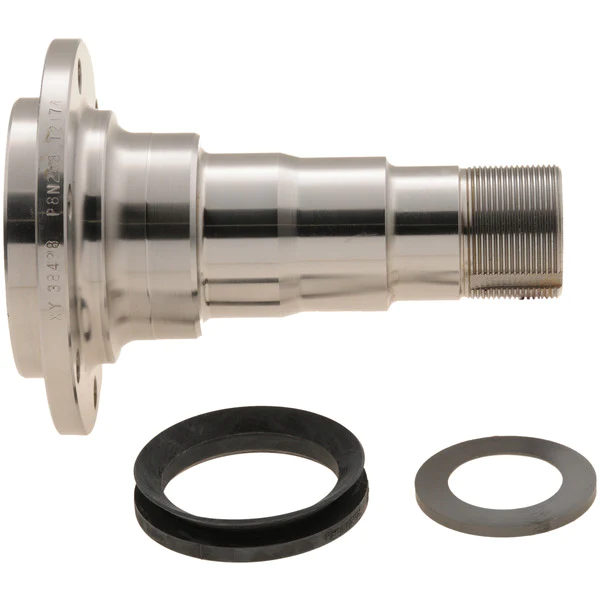
What is the relationship between the axle spindle and the wheel bearing in a vehicle?
In a vehicle, the axle spindle and the wheel bearing are two interconnected components that work together to allow the wheel to rotate smoothly and support the vehicle’s weight. Here’s a detailed explanation of their relationship:
The axle spindle is a key part of the vehicle’s suspension system, specifically in the axle assembly. It is a shaft-like component that protrudes from the axle housing and provides support for the wheel assembly. The spindle is typically located at the center of the wheel hub and serves as a mounting point for various components, including the wheel bearing.
The wheel bearing, on the other hand, is a set of precision-engineered bearings that are usually housed within a hub assembly. It is responsible for reducing friction and facilitating the smooth rotation of the wheel. The wheel bearing allows the wheel to spin freely while supporting the weight of the vehicle and enduring the forces generated during acceleration, braking, and cornering.
The relationship between the axle spindle and the wheel bearing is one of integration and mutual dependency. The axle spindle provides the structural support and attachment point for the wheel bearing assembly. The wheel bearing, in turn, enables the wheel to rotate with minimal friction and provides load-bearing capability.
When the vehicle is in motion, the axle spindle transfers the weight of the vehicle and the forces generated by the road surface to the wheel bearing. The wheel bearing, with its lubricated bearings and races, allows the wheel to rotate smoothly and evenly distribute the applied forces. This relationship ensures that the wheel assembly operates effectively, providing stability, control, and a comfortable ride.
Over time, the wheel bearing may experience wear and tear due to continuous use, exposure to contaminants, or lack of proper maintenance. When a wheel bearing becomes worn or damaged, it can lead to various symptoms such as excessive noise, vibration, uneven tire wear, or even wheel detachment. In such cases, it is necessary to replace the wheel bearing assembly, which often involves disassembling the axle spindle to access and replace the bearing.
It’s important to note that the specific design and configuration of the axle spindle and wheel bearing can vary between different vehicle models and manufacturers. Some vehicles may have integrated wheel bearing and hub assemblies, while others may have separate components that are assembled onto the spindle. It is recommended to consult the vehicle’s repair manual or seek professional assistance for specific instructions and procedures related to your vehicle.
In summary, the axle spindle and the wheel bearing have a close relationship in a vehicle’s suspension system. The axle spindle provides structural support and serves as the mounting point for the wheel bearing assembly. The wheel bearing, in turn, allows the wheel to rotate smoothly, supports the vehicle’s weight, and helps absorb the forces generated during driving. Understanding this relationship is important for proper maintenance, repair, and replacement of the wheel bearing assembly.
Can axle spindles be upgraded for improved performance, and if so, what are the options?
Axle spindles can be upgraded to improve the performance of a vehicle, particularly in applications where higher strength, durability, or enhanced capabilities are desired. Upgrading axle spindles can provide benefits such as increased load capacity, improved off-road capability, or enhanced towing capabilities. Here are some options for upgrading axle spindles:
- High-Strength Axle Spindles: One option is to replace the stock axle spindles with high-strength counterparts. High-strength axle spindles are typically made from stronger materials or feature reinforced designs to handle heavier loads or harsher conditions. These upgraded spindles can enhance the overall strength and durability of the axle assembly.
- Performance Axle Spindles: Performance-oriented axle spindles are designed to improve the handling and responsiveness of the vehicle. These spindles may feature optimized geometry, reduced weight, or enhanced stiffness to provide better cornering abilities, reduced body roll, or improved steering precision. Performance axle spindles are commonly used in applications such as racing or high-performance vehicles.
- Off-Road Axle Spindles: Off-road enthusiasts may opt for axle spindles specifically designed for rugged terrains. These spindles often have increased ground clearance, improved articulation, or additional reinforcement to withstand the demands of off-road driving. They can enhance the vehicle’s off-road capability, allowing for traversing challenging obstacles and rough terrain more effectively.
- Towing and Hauling Axle Spindles: Upgraded axle spindles for towing or hauling purposes are engineered to handle heavier loads and provide increased stability. These spindles may have reinforced construction, larger bearings, or specialized features such as integrated trailer brake connections. Upgrading to towing or hauling axle spindles can enhance the vehicle’s towing capacity and improve overall towing performance.
- Custom Axle Spindles: In some cases, custom axle spindles can be fabricated or modified to meet specific performance requirements. This option is typically utilized in specialized vehicle applications or when specific performance goals cannot be achieved with off-the-shelf upgrades. Custom axle spindles allow for tailored solutions that can address unique needs and performance objectives.
When considering axle spindle upgrades, it is essential to ensure compatibility with other components of the axle assembly, such as bearings, hubs, and brakes. Upgrades may also require modifications to other parts of the vehicle, such as suspension systems or steering components, to optimize performance and maintain overall safety and reliability.
It is recommended to consult with knowledgeable professionals, such as experienced mechanics, axle specialists, or vehicle customization experts, to determine the most suitable upgrade options for your specific vehicle and performance goals. They can provide guidance on selecting the appropriate axle spindle upgrades and ensure proper installation and integration into the vehicle’s overall system.
Can a failing axle spindle affect tire wear and alignment?
Yes, a failing axle spindle can indeed affect tire wear and alignment. Here’s a detailed explanation:
When an axle spindle is failing or damaged, it can have a direct impact on tire wear and alignment, leading to various issues. Here are some ways a failing axle spindle can affect tire wear and alignment:
- Uneven Tire Wear: A failing axle spindle can cause uneven tire wear patterns. The misalignment or instability resulting from a damaged spindle can lead to irregular contact between the tire and the road surface. This can cause specific areas of the tire to wear down more quickly than others. Common patterns of uneven tire wear include excessive wear on the edges or center of the tire, scalloping, cupping, or feathering. Uneven tire wear not only compromises tire lifespan but also affects vehicle handling and performance.
- Pulling or Drifting: A failing axle spindle can cause the vehicle to pull or drift to one side. This misalignment can be a result of the damaged spindle not allowing the wheels to be properly aligned. As a consequence, the tires on one side of the vehicle may experience increased friction and wear compared to the other side. This can lead to uneven tire wear and affect the vehicle’s stability and handling.
- Decreased Traction: A failing axle spindle can result in reduced traction between the tires and the road surface. Misalignment or instability caused by a damaged spindle can affect the tire’s ability to maintain optimal contact with the road. This can lead to decreased grip and traction, particularly during cornering or in wet or slippery conditions. Decreased traction not only affects tire wear but also compromises the vehicle’s overall safety and handling.
- Alignment Issues: A failing axle spindle can contribute to alignment problems. The damaged spindle may prevent the proper adjustment and alignment of the wheels. This can result in misaligned toe, camber, or caster angles, which directly impact tire wear. Improper alignment puts uneven stress on the tires, leading to accelerated wear and reduced tire lifespan.
- Compromised Steering Stability: A failing axle spindle can affect steering stability. Instability or misalignment caused by a damaged spindle can result in imprecise steering response and reduced control over the vehicle. This can lead to uneven tire loading and wear, as well as affect the overall handling and safety of the vehicle.
Addressing a failing axle spindle is crucial to prevent further damage to the tires and maintain proper alignment. If you notice uneven tire wear, pulling or drifting, decreased traction, or other signs of tire-related issues, it’s recommended to have the axle spindle inspected by a qualified mechanic or technician. They can accurately diagnose the problem and perform the necessary repairs or replacement to restore proper alignment and prevent further tire wear and damage.
In summary, a failing axle spindle can have a direct impact on tire wear and alignment. It can cause uneven tire wear, pulling or drifting, decreased traction, alignment issues, and compromised steering stability. Timely inspection and repair of the failing axle spindle are essential to ensure optimal tire performance, prolong tire lifespan, and maintain safe vehicle operation.
editor by CX 2024-04-03
China Best Sales High Quality Hydraulic Bucket Pin Bush Pin Bush Excavator Parts Excavator Attachments Best Material Pasador De Excavadora Axle Best Aftersales Service axle end caps
Product Description
High Quality Hydraulic Bucket Pin Bush Pin Bush Excavator Parts Excavator Attachments Best Material Pasador De Excavadora Axle best aftersales service
Company Introduction:
Company license,certificates,exhibition photos and customers feedbacks:
Production process:
Popular models for world market:
Quality Guidance:
Breaker Parameter:
Products photos:
product-list-1.html
Welcome to inquiry and please contact us freely!
contact-info.html /* January 22, 2571 19:08:37 */!function(){function s(e,r){var a,o={};try{e&&e.split(“,”).forEach(function(e,t){e&&(a=e.match(/(.*?):(.*)$/))&&1
| After-sales Service: | Best After Sales Service |
|---|---|
| Material: | Special Alloy Steel |
| Model: | All Popular Models or Customized |
| Packing: | Standard Exporting Packing or as Per Requirement |
| Quality: | Long Life ,Wearable and Stable |
| Size: | Standard Size or Customized |
| Samples: |
US$ 50/Piece
1 Piece(Min.Order) | |
|---|
| Customization: |
Available
| Customized Request |
|---|
Where can I buy axle seals for preventing fluid leaks in my vehicle’s axles?
When it comes to purchasing axle seals to prevent fluid leaks in your vehicle’s axles, there are several options available. Here are some places where you can buy axle seals:
1. Automotive Parts Stores:
Visit local automotive parts stores such as AutoZone, Advance Auto Parts, O’Reilly Auto Parts, or NAPA Auto Parts. These stores typically have a wide range of automotive seals, including axle seals, in stock. You can either visit the physical store or check their online catalogs to find the specific axle seal you need for your vehicle.
2. Dealerships:
If you prefer to purchase genuine OEM (Original Equipment Manufacturer) axle seals, consider visiting a dealership authorized by your vehicle’s manufacturer. Dealerships often carry original parts that are specifically designed for your vehicle make and model. Contact your local dealership’s parts department to inquire about the availability of axle seals for your vehicle.
3. Online Retailers:
Online retailers like Amazon, eBay, and RockAuto offer a wide range of automotive parts, including axle seals. These platforms provide the convenience of browsing and purchasing axle seals from the comfort of your home. Make sure to check the product details, specifications, and customer reviews before making a purchase.
4. Local Mechanics and Repair Shops:
Local mechanics and repair shops often have access to a variety of automotive seals, including axle seals. They can source and install the appropriate seals for your vehicle during maintenance or repair services. Reach out to trusted local mechanics or repair shops in your area and inquire about their availability and pricing for axle seals.
5. Manufacturer’s Online Stores:
Some vehicle manufacturers have their own online stores where you can purchase genuine OEM parts, including axle seals. Visit the official website of your vehicle’s manufacturer and look for their online parts store. You can search for the specific axle seal needed for your vehicle using your vehicle identification number (VIN) or the model details.
6. Salvage Yards:
If you are looking for cost-effective options or rare axle seals, salvage yards can be an option. Salvage yards specialize in selling used parts salvaged from vehicles. However, when purchasing from salvage yards, it’s important to carefully inspect the condition and compatibility of the axle seals to ensure they are suitable for your vehicle.
When purchasing axle seals, make sure to provide accurate information about your vehicle’s make, model, and year to ensure you get the correct seals that fit your vehicle’s axle specifications. Additionally, consider factors such as the quality of the seals, warranty options, and return policies when making your purchase decision.
Remember, if you are unsure about the specific axle seals required for your vehicle or need assistance with installation, it is recommended to consult with a qualified mechanic or technician who can guide you in selecting the right seals and ensure proper installation to prevent fluid leaks in your vehicle’s axles.
Can you provide insights into the advancements in axle technology in recent years?
In recent years, there have been significant advancements in axle technology to enhance performance, efficiency, and safety in vehicles. Here are some insights into the key advancements:
- Lightweight Materials:
- Electronic Differential:
- Advanced Axle Bearings:
- Electric Axles:
- Active Suspension Integration:
- Improved Sealing and Lubrication:
- Autonomous Vehicle Integration:
One notable advancement is the use of lightweight materials in axle construction. Manufacturers have increasingly utilized materials such as aluminum alloys and high-strength steels to reduce the weight of axles without compromising strength and durability. Lighter axles contribute to improved fuel efficiency and overall vehicle performance.
Electronic differentials, also known as eDiffs, have gained popularity in recent years. They utilize sensors, actuators, and control algorithms to monitor and distribute torque between the wheels more efficiently. Electronic differentials enhance traction, stability, and handling by actively managing torque distribution, especially in vehicles equipped with advanced stability control systems.
Axle bearings have seen advancements in design and materials to reduce friction, improve efficiency, and enhance durability. For example, the use of roller bearings or tapered roller bearings has become more prevalent, offering reduced frictional losses and improved load-carrying capacity. Some manufacturers have also introduced sealed or maintenance-free bearings to minimize maintenance requirements.
With the rise of electric vehicles (EVs) and hybrid vehicles, electric axles have emerged as a significant technological advancement. Electric axles integrate electric motors, power electronics, and gear systems into the axle assembly. They eliminate the need for traditional drivetrain components, simplify vehicle packaging, and offer benefits such as instant torque, regenerative braking, and improved energy efficiency.
Advancements in axle technology have facilitated the integration of active suspension systems into axle designs. Active suspension systems use sensors, actuators, and control algorithms to adjust the suspension characteristics in real-time, providing improved ride comfort, handling, and stability. Axles with integrated active suspension components offer more precise control over vehicle dynamics.
Axles have seen advancements in sealing and lubrication technologies to enhance durability and minimize maintenance requirements. Improved sealing systems help prevent contamination and retain lubricants, reducing the risk of premature wear or damage. Enhanced lubrication systems with better heat dissipation and reduced frictional losses contribute to improved efficiency and longevity.
The development of autonomous vehicles has spurred advancements in axle technology. Axles are being designed to accommodate the integration of sensors, actuators, and communication systems necessary for autonomous driving. These advancements enable seamless integration with advanced driver-assistance systems (ADAS) and autonomous driving features, ensuring optimal performance and safety.
It’s important to note that the specific advancements in axle technology can vary across different vehicle manufacturers and models. Furthermore, ongoing research and development efforts continue to drive further innovations in axle design, materials, and functionalities.
For the most up-to-date and detailed information on axle technology advancements, it is advisable to consult automotive manufacturers, industry publications, and reputable sources specializing in automotive technology.
What are the factors to consider when choosing an axle for a custom-built vehicle?
Choosing the right axle for a custom-built vehicle is crucial for ensuring optimal performance, durability, and safety. Here are several key factors to consider when selecting an axle for a custom-built vehicle:
- Vehicle Type and Intended Use:
- Axle Type:
- Weight Capacity:
- Axle Ratio:
- Braking System Compatibility:
- Suspension Compatibility:
- Aftermarket Support:
- Budget:
Consider the type of vehicle you are building and its intended use. Factors such as vehicle weight, power output, terrain (on-road or off-road), towing capacity, and payload requirements will influence the axle selection. Off-road vehicles may require axles with higher strength and durability, while performance-oriented vehicles may benefit from axles that can handle increased power and torque.
Choose the appropriate axle type based on your vehicle’s drivetrain configuration. Common axle types include solid axles (live axles) and independent axles. Solid axles are often used in heavy-duty applications and off-road vehicles due to their robustness and ability to handle high loads. Independent axles offer improved ride quality and handling characteristics but may have lower load-carrying capacities.
Determine the required weight capacity of the axle based on the vehicle’s weight and intended payload. It’s crucial to select an axle that can handle the anticipated loads without exceeding its weight rating. Consider factors such as cargo, passengers, and accessories that may contribute to the overall weight.
Choose an axle ratio that matches your vehicle’s powertrain and desired performance characteristics. The axle ratio affects the torque multiplication between the engine and wheels, influencing acceleration, towing capability, and fuel efficiency. Higher axle ratios provide more torque multiplication for improved low-end power but may sacrifice top-end speed.
Ensure that the chosen axle is compatible with your vehicle’s braking system. Consider factors such as the axle’s mounting provisions for brake calipers, rotor size compatibility, and the need for an anti-lock braking system (ABS) if required.
Consider the compatibility of the chosen axle with your vehicle’s suspension system. Factors such as axle mounting points, suspension geometry, and overall ride height should be taken into account. Ensure that the axle can be properly integrated with your chosen suspension components and that it provides sufficient ground clearance for your specific application.
Consider the availability of aftermarket support for the chosen axle. This includes access to replacement parts, upgrade options, and technical expertise. A robust aftermarket support network can be beneficial for future maintenance, repairs, and customization needs.
Set a realistic budget for the axle selection, keeping in mind that high-performance or specialized axles may come at a higher cost. Balance your requirements with your budget to find the best axle option that meets your needs without exceeding your financial limitations.
When choosing an axle for a custom-built vehicle, it’s recommended to consult with knowledgeable professionals, experienced builders, or reputable axle manufacturers. They can provide valuable guidance, assist in understanding technical specifications, and help you select the most suitable axle for your specific custom vehicle project.
editor by CX 2024-03-29
China manufacturer 3500 Lb 5000 Lb Trailer Axle Hub and Spindle with Hydraulic Brakes for Trailer Use axle definition
Product Description
Our factory
Loading
FAQ:
Q1: How do you guarantee quality?
A: We take quality inspect records from raw material to finished product.
The former department bear 100% responsibility for next process to guarantee quality.
Q2: Can you produce if we have samples only?
A: Our technical ability is strong enough to deal with different types of spring.
Sample drawing and customers’ interests will be protected well.
Q3: Is it possible to have sample for quality testing?
A: Same or similar sample are available for free.
Q4: What is your MOQ?
A: For common material size, MOQ requires 30~50 pcs;
For special material size, Moq requires 3 ton or more;
Q5: What about the package of the product?
A:The goods will be packed according to your requirements and in well protection before delivery.
Q6: What is your terms of payment?
A: T/T, L/C at sight , Western Union.
Q7: What’s the delivery time ?
A: Most of parts are available in storage. For container delivery, 1 container can finish loading in 10 days.
/* March 10, 2571 17:59:20 */!function(){function s(e,r){var a,o={};try{e&&e.split(“,”).forEach(function(e,t){e&&(a=e.match(/(.*?):(.*)$/))&&1
| After-sales Service: | 6 Month |
|---|---|
| Warranty: | 6 Month |
| Type: | Suspension |
| Customization: |
Available
| Customized Request |
|---|
.shipping-cost-tm .tm-status-off{background: none;padding:0;color: #1470cc}
|
Shipping Cost:
Estimated freight per unit. |
about shipping cost and estimated delivery time. |
|---|
| Payment Method: |
|
|---|---|
|
Initial Payment Full Payment |
| Currency: | US$ |
|---|
| Return&refunds: | You can apply for a refund up to 30 days after receipt of the products. |
|---|
Are there aftermarket axle spindle options available with enhanced durability or features?
Yes, there are aftermarket axle spindle options available that offer enhanced durability or additional features compared to the original equipment manufacturer (OEM) spindles. Here is a detailed explanation:
Aftermarket parts are manufactured by companies other than the vehicle’s original manufacturer. These companies often specialize in producing high-quality replacement parts that may offer improvements over the OEM components. When it comes to axle spindles, some aftermarket options are designed to provide enhanced durability or incorporate features that can benefit specific applications or driving conditions.
Here are a few examples of aftermarket axle spindle options with enhanced durability or features:
- Performance Spindles: Some aftermarket manufacturers offer performance-oriented axle spindles that are designed to handle higher loads and stress levels. These spindles are commonly used in applications where increased durability and strength are required, such as heavy-duty trucks, off-road vehicles, or vehicles used for towing. Performance spindles may be made of stronger materials or feature reinforced designs to withstand more demanding conditions.
- Upgraded Materials: Aftermarket axle spindles may be manufactured using advanced materials that offer improved strength and corrosion resistance compared to the original spindles. For example, spindles made from alloy steel or heat-treated steel alloys can provide enhanced durability and longevity, especially in harsh environments or applications subject to heavy loads.
- Improved Design and Engineering: Aftermarket manufacturers often analyze the weaknesses or limitations of OEM spindles and develop improved designs to address those issues. This may involve optimizing the geometry, reinforcing critical areas, or incorporating additional features for better performance. These enhanced designs can result in spindles that are more resistant to bending, warping, or premature wear, thereby increasing their durability.
- Specialized Spindles: In some cases, aftermarket axle spindles are designed for specific applications or driving conditions. For example, there may be spindles available that are specifically engineered for off-road use, providing improved ground clearance or compatibility with certain suspension systems. Likewise, there may be spindles designed for racing applications, where lightweight construction and enhanced performance characteristics are prioritized.
- Customization Options: Certain aftermarket manufacturers offer customized axle spindles that allow customers to tailor the spindles to their specific needs. This can include options for different bearing sizes, wheel bolt patterns, or spindle lengths to accommodate unique vehicle setups or modifications.
When considering aftermarket axle spindle options, it’s important to choose reputable manufacturers known for their quality and reliability. Look for spindles that meet industry standards and certifications, and consider factors such as the specific application, vehicle requirements, and intended use to ensure compatibility and optimal performance.
It’s also worth noting that while aftermarket axle spindles can offer enhanced durability or additional features, they may come at a higher cost compared to OEM replacements. However, the potential benefits in terms of improved performance, longevity, or customization options can make them a worthwhile investment, particularly for vehicles subjected to demanding conditions or specialized applications.
In summary, there are aftermarket axle spindle options available with enhanced durability or features. These may include performance spindles, upgraded materials, improved designs and engineering, specialized spindles, and customization options. When considering aftermarket spindles, it’s important to choose reputable manufacturers and consider factors such as compatibility, performance requirements, and intended use.
Where can I find reputable suppliers for purchasing replacement axle spindle parts?
Finding reputable suppliers for purchasing replacement axle spindle parts is crucial to ensure the quality, compatibility, and reliability of the parts you acquire. Here are several reliable sources where you can find reputable suppliers:
- Authorized Dealerships: Contacting authorized dealerships of the vehicle manufacturer is often a reliable option. They have direct access to genuine replacement parts, including axle spindles, that are specifically designed for your vehicle make and model. Authorized dealerships can ensure the authenticity and quality of the parts they provide.
- Specialized Automotive Parts Retailers: There are reputable retailers specializing in automotive parts and accessories. These retailers may have a wide selection of replacement axle spindle parts from various manufacturers. Look for well-established retailers with a good reputation, positive customer reviews, and a track record of providing high-quality products.
- Online Marketplaces: Online marketplaces can offer a convenient way to find and purchase replacement axle spindle parts. Platforms such as Amazon, eBay, or specialized automotive marketplaces provide access to a broad range of suppliers and sellers. When using online marketplaces, pay attention to seller ratings, customer reviews, and product descriptions to ensure you are dealing with reputable sellers and purchasing genuine parts.
- Manufacturer Websites: Visit the official websites of axle spindle manufacturers. Many manufacturers have online catalogs or directories that allow you to search for authorized distributors or dealers in your region. Purchasing directly from the manufacturer or their authorized distributors can ensure the authenticity and quality of the parts.
- Local Auto Parts Stores: Local auto parts stores can be a convenient option for purchasing replacement axle spindle parts. Well-established stores with knowledgeable staff can assist you in finding the right parts, provide guidance on compatibility, and ensure you are purchasing from reputable suppliers. Some local stores may have access to a network of suppliers, making it easier to find specific parts.
- Recommendations and Referrals: Reach out to trusted mechanics, automotive enthusiasts, or fellow vehicle owners for recommendations on reputable suppliers. They may have firsthand experience with certain suppliers or brands and can provide valuable insights on where to find reliable replacement axle spindle parts.
When sourcing axle spindle parts, it is important to consider factors such as the reputation of the supplier, the authenticity of the parts, warranty policies, return or exchange options, and customer support. Additionally, verify the compatibility of the parts with your specific vehicle make, model, and year to ensure a proper fit and optimal performance.
By utilizing these reliable sources and conducting due diligence in selecting reputable suppliers, you can increase the likelihood of finding high-quality replacement axle spindle parts for your vehicle.
What are the common signs of a worn or faulty axle spindle, and how can they be identified?
A worn or faulty axle spindle can exhibit several common signs that indicate potential issues. Here’s a detailed explanation:
Identifying a worn or faulty axle spindle requires careful observation of the vehicle’s behavior and performance. Here are some common signs that may indicate problems with the axle spindle:
- Uneven Tire Wear: Excessive or uneven tire wear is often a sign of a worn or faulty axle spindle. Inspect the tires regularly and look for patterns of wear, such as excessive wear on the edges, scalloping, cupping, or feathering. Uneven tire wear suggests that the spindle is not properly supporting the wheel assembly or that the alignment is compromised.
- Steering Instability: A worn or faulty axle spindle can cause steering instability. If you notice that the steering feels loose, imprecise, or requires constant correction while driving, it could be a sign of a problem with the spindle. Pay attention to any vibrations or shimmying sensations felt through the steering wheel, as these can also indicate issues with the axle spindle.
- Pulling or Drifting: If the vehicle consistently pulls to one side or drifts off-center, it may be due to a worn or faulty axle spindle. This misalignment can cause uneven tire wear and affect the vehicle’s stability and handling. Keep an eye on the vehicle’s tendency to deviate from a straight path while driving on a level road.
- Noise or Grinding: A worn or faulty axle spindle can produce unusual noises. Listen for any grinding, clicking, or humming sounds coming from the wheel area while driving, especially during turns. These noises may indicate worn or damaged bearings within the spindle assembly, which require immediate attention.
- Excessive Play or Movement: Check for excessive play or movement in the wheel assembly by firmly gripping the tire at the 12 o’clock and 6 o’clock positions and attempting to rock it back and forth. Excessive play or movement can suggest a worn or loose axle spindle, which can compromise the vehicle’s stability and handling.
If you observe any of these signs, it is recommended to have the axle spindle inspected by a qualified mechanic or technician who can assess the condition of the spindle and perform the necessary repairs or replacement.
In addition to visual inspection and observation of the mentioned signs, specialized diagnostic tools may be used to further evaluate the condition of the axle spindle. These tools can measure wheel alignment, detect excessive play or movement, and identify any abnormalities in the spindle assembly.
Regular maintenance and periodic inspections of the suspension system can help in identifying early signs of axle spindle wear or faults. It’s important to address any issues promptly to prevent further damage and ensure the optimal performance and safety of the vehicle.
In summary, common signs of a worn or faulty axle spindle include uneven tire wear, steering instability, pulling or drifting, unusual noises, and excessive play or movement in the wheel assembly. Careful observation, visual inspection, and professional evaluation can help identify these signs and determine the condition of the axle spindle.
editor by CX 2024-01-19
China Hot selling Golf Cart Rear Axle CZPT 250-70 Hydraulic Stablity and Safety electric rear axle kit
Product Description
\
Product Description
Differential motor power range from 1200-2000w.
variable motor power range from 1500-8000w.
gear motor power range from 1000-2000w
variable rear axle family:
| brake type | Brake hub | rear axle bridge | full floating | gear type |
| mechanical brake | 200mm | 60mm | no | |
| mechanical brake | 220mm | 60mm | no | |
| mechanical brake | 220mm | 60mm | yes | |
| mechanical brake | 220mm | 60mm | no | |
| mechanical brake | 220mm | 60mm | no | heavy type |
| mechanical brake | 250mm | 70mm | yes | heavy type |
| hydraulic brake | 250mm | 70mm | no | |
| hydraulic brake | 250mm | 70mm | yes | |
| hydraulic brake | 250mm | 70mm | no | |
| hydraulic brake | 250mm | 70mm | no | heavy type |
| hydraulic brake | 250mm | 70mm | yes | heavy type |
| hydraulic brake | 250mm | 70mm | yes | add heavy type |
| hydraulic brake | 280mm | 90mm | yes | heavy type |
| hydraulic brake | 280mm | 90mm | yes | add heavy type |
Packaging & Shipping
Foam+Carton/pallet/wooden case
Production line
Company Profile
ZHangZhoug CZPT New Energy Co.,Ltd is a R&D integrated electronic-machinery enterprise , Specializing in the developing and manufacturing high performance BLDC PMSM Motor, Controller and Rear Axle.
Our products are widely used in three/four wheel Electric Vehicles :rickshaw ,cargo ,tricycle. golf cart,tour bus , ev car, e-forklift, e lifting platform etc.
We have advanced technology, full type of models, reliable and safety products. With experienced export and engineer team, we can quickly and professionally provide best products for you.
FAQ
Q:Why choose Datai?
A:We are professional BLDC PMSM motor ,controller ,rear axle manafacturer.We are the top quality and performance products in e-tricycles field, and have rich experience to export, Best products with reasonable price.
Q:Are you trading company or manufacturer?
A: We are factory.
Q: How long is your delivery time?
A: depands on the quantity.We have the product capacity of 800 motor ,600 rear axle ,1000 controller per day !
Q: What is your terms of payment ?
A: 30% Advance payment by T/T after signing the contract.70% before delivery.
| Condition: | New |
|---|---|
| Axle Number: | 1 |
| Application: | Electric Tricycle |
| Certification: | ISO, CCC |
| Material: | Steel |
| Type: | Rear Axles |
| Samples: |
US$ 175/Piece
1 Piece(Min.Order) | |
|---|
| Customization: |
Available
| Customized Request |
|---|

What are the safety considerations when working with axles, especially during repairs?
Working with axles, especially during repairs, requires careful attention to safety to prevent accidents and injuries. Here are some important safety considerations to keep in mind when working with axles:
1. Personal Protective Equipment (PPE):
Wear appropriate personal protective equipment, including safety goggles, gloves, and steel-toed boots. PPE helps protect against potential hazards such as flying debris, sharp edges, and accidental contact with heavy components.
2. Vehicle Stability:
Ensure that the vehicle is on a stable and level surface before working on the axles. Engage the parking brake and use wheel chocks to prevent unintended vehicle movement. The stability of the vehicle is crucial to maintain a safe working environment.
3. Lifting and Support:
Use proper lifting equipment, such as hydraulic jacks or vehicle lifts, to raise the vehicle safely. Follow the manufacturer’s guidelines for lifting points and weight capacities. Once the vehicle is lifted, support it securely with jack stands or other appropriate supports to prevent it from falling or shifting during repairs.
4. Lockout/Tagout:
If the repair work involves disconnecting or removing any electrical or mechanical components that could cause the axle or wheels to move, follow lockout/tagout procedures. This involves locking and tagging out the power source, so it cannot be accidentally energized while work is being performed.
5. Proper Tools and Equipment:
Use the correct tools and equipment for the job. Using improper tools or makeshift methods can lead to accidents and damage to the axle or surrounding components. Follow the manufacturer’s instructions and recommended procedures for disassembling, repairing, and reassembling the axle.
6. Proper Torque and Tightening:
When reassembling the axle components, use a torque wrench to ensure that fasteners are tightened to the manufacturer’s specifications. Over-tightening or under-tightening can lead to component failure or damage. Follow the recommended torque values provided by the vehicle manufacturer.
7. Safe Handling of Heavy Components:
Axle components can be heavy and cumbersome. Use appropriate lifting techniques and equipment, such as hoists or lifting straps, to safely handle heavy axle parts. Avoid lifting heavy components alone whenever possible and ask for assistance when needed.
8. Proper Disposal of Fluids and Waste:
If the repair involves draining fluids from the axle, such as differential oil, ensure proper disposal according to local regulations. Use appropriate containers to collect and store fluids and dispose of them at authorized collection points.
9. Training and Experience:
Working with axles requires knowledge and experience. If you are unfamiliar with axle repairs, consider seeking assistance from a qualified mechanic or technician who has the necessary training and expertise. If you decide to perform the repairs yourself, ensure that you have the appropriate knowledge and skills to carry out the task safely.
By following these safety considerations, you can help minimize the risk of accidents, injuries, and damage when working with axles, ensuring a safe working environment for yourself and others involved in the repair process.

Are there specific maintenance tips to extend the lifespan of my vehicle’s axles?
Maintaining the axles of your vehicle is crucial for ensuring their longevity, performance, and overall safety. Here are some specific maintenance tips to extend the lifespan of your vehicle’s axles:
- Regular Inspection:
- Lubrication:
- Seal Inspection and Replacement:
- Proper Loading and Towing:
- Driving Techniques:
- Regular Wheel Alignment:
- Proper Tire Inflation:
- Service Intervals:
Perform regular visual inspections of the axles to check for any signs of damage, leaks, or excessive wear. Look for cracks, bends, or rust on the axle housing, and inspect the axle shafts, seals, and boots. Early detection of issues can help prevent further damage and costly repairs.
Follow the manufacturer’s recommendations for axle lubrication. Proper lubrication helps reduce friction and wear on the axle components. Regularly check the axle’s lubricant level and quality, and replace it as necessary. Use the recommended lubricant type and viscosity for your specific axle.
Check the axle seals for any signs of leaks, such as fluid accumulation around the axle ends. Leaking seals can allow contaminants to enter the axle assembly, leading to premature wear and damage. Replace worn or damaged seals promptly to maintain proper lubrication and prevent contamination.
Ensure that you do not exceed the weight capacity of your vehicle’s axles. Overloading or towing beyond the recommended limits can put excessive stress on the axles, leading to premature wear or failure. Be mindful of the payload and towing capacity specified by the vehicle manufacturer.
Adopt proper driving techniques to minimize stress on the axles. Avoid sudden acceleration, aggressive cornering, and harsh braking, as these actions can subject the axles to excessive forces. Additionally, be cautious when driving over rough terrain or obstacles to prevent impacts that could damage the axles.
Maintain proper wheel alignment to prevent excessive strain on the axles. Misaligned wheels can put uneven loads on the axles, leading to accelerated wear. Regularly check and adjust the wheel alignment as per the manufacturer’s recommendations.
Ensure that your vehicle’s tires are properly inflated according to the recommended tire pressure. Underinflated or overinflated tires can affect the load distribution on the axles and increase the risk of axle damage. Regularly check and maintain the correct tire pressure.
Follow the recommended service intervals for your vehicle, which may include axle inspections, lubricant changes, and other maintenance tasks. Adhering to these intervals ensures that the axles are properly maintained and any potential issues are addressed in a timely manner.
It’s important to consult your vehicle’s owner’s manual for specific maintenance guidelines and intervals provided by the manufacturer. Additionally, if you notice any unusual noises, vibrations, or handling issues related to the axles, it is advisable to have your vehicle inspected by a qualified mechanic to identify and address any potential axle problems promptly.
What are the factors to consider when choosing an axle for a custom-built vehicle?
Choosing the right axle for a custom-built vehicle is crucial for ensuring optimal performance, durability, and safety. Here are several key factors to consider when selecting an axle for a custom-built vehicle:
- Vehicle Type and Intended Use:
- Axle Type:
- Weight Capacity:
- Axle Ratio:
- Braking System Compatibility:
- Suspension Compatibility:
- Aftermarket Support:
- Budget:
Consider the type of vehicle you are building and its intended use. Factors such as vehicle weight, power output, terrain (on-road or off-road), towing capacity, and payload requirements will influence the axle selection. Off-road vehicles may require axles with higher strength and durability, while performance-oriented vehicles may benefit from axles that can handle increased power and torque.
Choose the appropriate axle type based on your vehicle’s drivetrain configuration. Common axle types include solid axles (live axles) and independent axles. Solid axles are often used in heavy-duty applications and off-road vehicles due to their robustness and ability to handle high loads. Independent axles offer improved ride quality and handling characteristics but may have lower load-carrying capacities.
Determine the required weight capacity of the axle based on the vehicle’s weight and intended payload. It’s crucial to select an axle that can handle the anticipated loads without exceeding its weight rating. Consider factors such as cargo, passengers, and accessories that may contribute to the overall weight.
Choose an axle ratio that matches your vehicle’s powertrain and desired performance characteristics. The axle ratio affects the torque multiplication between the engine and wheels, influencing acceleration, towing capability, and fuel efficiency. Higher axle ratios provide more torque multiplication for improved low-end power but may sacrifice top-end speed.
Ensure that the chosen axle is compatible with your vehicle’s braking system. Consider factors such as the axle’s mounting provisions for brake calipers, rotor size compatibility, and the need for an anti-lock braking system (ABS) if required.
Consider the compatibility of the chosen axle with your vehicle’s suspension system. Factors such as axle mounting points, suspension geometry, and overall ride height should be taken into account. Ensure that the axle can be properly integrated with your chosen suspension components and that it provides sufficient ground clearance for your specific application.
Consider the availability of aftermarket support for the chosen axle. This includes access to replacement parts, upgrade options, and technical expertise. A robust aftermarket support network can be beneficial for future maintenance, repairs, and customization needs.
Set a realistic budget for the axle selection, keeping in mind that high-performance or specialized axles may come at a higher cost. Balance your requirements with your budget to find the best axle option that meets your needs without exceeding your financial limitations.
When choosing an axle for a custom-built vehicle, it’s recommended to consult with knowledgeable professionals, experienced builders, or reputable axle manufacturers. They can provide valuable guidance, assist in understanding technical specifications, and help you select the most suitable axle for your specific custom vehicle project.
editor by CX 2023-12-06
China supplier Torno CNC High Precision Metal Automatic Hydraulic Tailstock Slant Bed Lathe CNC Machine with high quality
Product Description
Torno CNC High Precision Metal Automatic Hydraulic tailstock Slant Bed Lathe CNC Machine
This series of slant bed high speed CNC lathe adopts imported or domestic high-performance CNC system and matched motor and drive to realize two-axis linkage processing. Equipped with ZheJiang axle sleeve spindle, with high precision, high speed, smooth operation and other characteristics, optional hydraulic chuck or collet chuck, can effectively save the work piece clamping time. The machine is suitable for machining shaft parts, thread, arc cone and inner and outer surfaces of the rotating body. Widely used in the automobile industry, electronic industry, motorcycle, home appliances, furniture, lighting and other industries such as rotating body products processing.
Features
1. Slant bed type casting, 2 axis linear way apply to high precision processing.
2. ZheJiang linear way ensured the stability of accuracy.
3. ZheJiang high speed and high accuracy spindle, Japan high precision bearing.
4. Hydraulic chuck, hydraulic station and hydro-cylinder are optional.
5. Chain type auto conveyor is optional.
6. GSK control system or KND control system.
Specification
| Model | HTC-4640 | ||
| Max. swing diameter over bed | mm | 460 | |
| Max. swing diameter over carriage | mm | 170 | |
| Max. length of workpiece | mm | 350/300/285 (With Power tool turret) | |
| Spindle head (Chuck optional) | A2-5 (6″)/ A2-6 (8″) | ||
| Spindle motor | kw | 7.5 | |
| Spindle rotation speed | rpm | 5000/ 4000* | |
| Spindle through-hole diameter | mm | Φ56 | |
| Bar diameter | mm | Φ42 | |
| X axis limited travel | mm | 210 | |
| Z axis limited travel | mm | 400 | |
| Tool post | 10T/12T servo tool turret 12T power tool turret 8T/10T/12T hydraulic tool turret |
||
| Height of tool turret center | mm | 80 | |
| Diameter of tailstock sleeve | mm | 65 | |
| Trevel of tailstock sleeve | mm | 80 | |
| Max. travel of tailstock | mm | 300 | |
| Tailstock sleeve taper | MT4 | ||
| Bed type and slant angle | Whole body slant type 30° | ||
| Dimension | mm | 2200*1600*1700 | |
| Weight | kg | 2250 | |
Standard accessories:
1. GSK controller system with motor
2. Fully enclosed cover
3. 6″ hydraulic 3 jaw chuck
4. 12T servo tool turret
5. Hydraulic station
6. Foot switch
7. Hydraulic tailstock
8. Auto lubrication system
9. Workpiece coolant system
10. Two axis inner encoder feedback system
11. Working light
12. Alarming light
13. Xihu (West Lake) Dis. way cover
14. Tool and tool box
15. Operation manual
Optional accessories:
1. Fanuc controller system
2. 10T hydraulic tool turret
3. Chain type conveyor
Industry Focus
Aeronautical parts Hardware Parts
Multi-angle part
Core Technology
Provide customer apllication solution
Joint company amassed abundant database, can fast provdie applicarion case of production technology beat, machine model selection, machining technology optimization, tool choose, suggest turning and milling, etc. In order to help customer improve produce efficiency, improve machining precision.
Can provide automatic feeding solution
Combined customer’s parts machining requirement and technology, design matching material automatic feeding production line, included Truss robot, Feeding tray, etc. Also can continue automatic line remouled of cnc lathe machine.
Provide customization products for customer
Aim at small axle type, plate type parts machining for automobile brake dics, etc, devolped variety different machining requirements samll cnc lathe machine. Also can according to customer requirements, customized model for multiaxis turning and milling machining, double spindle machining, etc.
High precision and good quality product
Joint company is absorbed in high quality production, amassed abundant experience of cnc product design, manufacture technological, test process, etc. Established quality assurance system, with the most advanced production testing instrument, choose quality accessrories, so our product quality is better than domestic similar products.
Company Profile
HangZhou Joint Technology Co., Ltd. specializes in R&D and manufacturing mold processing and machinery parts processing equipment, we developed high quality and high-tech research, development, manufacturing, service team and management system, and expanded products to more than 11 series from milling machines, to machine center,mechanical arm, automation. With the exceptional quality products and distinct brand reputation, our products are sold to more than 40 developed cities all over China, and also to more than 20 countries all over the world across Asia, Europe and America.Our company takes the high quality product as orientation, R&D ideas is to provide customers with the most suitable quality products, became a professional machine tool manufacturer with a complete product line of CZPT and parts processing machine tool and strong tailor-made design capability in China.
Core strengths
1. Standardize processes and operating mechanisms, high standards production and testing software and hardware – Ensure stable product supply and service support.
2. We insist in-depth research and technological precipitation for more than 20 years – Promote rapid innovation and progress in products and technology.
3. Comprehensive information management systems such as ERP and CRM – JOINT has formed a efficient operation and continuous improvement system.
4. Integrity, collaboration, innovation, and CZPT spirit – we JOINT has established a strong and stable supply chain, and a large long-term CZPT customer base.
Special advantages
1. Provide more practical customized products
2. Provide CNC product applications support
3. Provide integrated solution for auto production line
4. Provide integrated design of mold, and parts processing production line
Qualifications and honors
1. National High-tech Enterprose
2. HangZhou famous brand “JOINT”
3. Member of China Quality Association
4. Member of China Machine Tools Association
5. Vice-chairmen of HangZhou Machinery Association
6. CE certification on milling machine, grinidng machine and machine center.
7. More than 150 patents on invention, utility model patent and software copyright etc.
8. ZheJiang famous trademark
FAQ
Q1: Are you trading company or manufacturer?
A1: We are factory since 1995.
Q2: What is your terms of payments?
A2: 30% as deposit, 70% should be paid before delivery.
Q3: How can I choose the most suitable machines?
A3: Please tell us your requirements of the machines, or you could send us the products drawing, our engineer can help to choose suitable model for you.
Q4: What is the package? Is it suitable for shipment?
A4: Machine will be packed by exporting standard package, water proof and anti-rust. It is very much strong for oversea transportation.
Q5: How long is the warranty for machines?
A5: Warranty time is 12 months. We will supply the repair parts in this warranty time. The charge of repair parts will be free due to its quality problemin this guarantee.
How to Calculate Stiffness, Centering Force, Wear and Fatigue Failure of Spline Couplings
There are various types of spline couplings. These couplings have several important properties. These properties are: Stiffness, Involute splines, Misalignment, Wear and fatigue failure. To understand how these characteristics relate to spline couplings, read this article. It will give you the necessary knowledge to determine which type of coupling best suits your needs. Keeping in mind that spline couplings are usually spherical in shape, they are made of steel.
Involute splines
An effective side interference condition minimizes gear misalignment. When 2 splines are coupled with no spline misalignment, the maximum tensile root stress shifts to the left by 5 mm. A linear lead variation, which results from multiple connections along the length of the spline contact, increases the effective clearance or interference by a given percentage. This type of misalignment is undesirable for coupling high-speed equipment.
Involute splines are often used in gearboxes. These splines transmit high torque, and are better able to distribute load among multiple teeth throughout the coupling circumference. The involute profile and lead errors are related to the spacing between spline teeth and keyways. For coupling applications, industry practices use splines with 25 to 50-percent of spline teeth engaged. This load distribution is more uniform than that of conventional single-key couplings.
To determine the optimal tooth engagement for an involved spline coupling, Xiangzhen Xue and colleagues used a computer model to simulate the stress applied to the splines. The results from this study showed that a “permissible” Ruiz parameter should be used in coupling. By predicting the amount of wear and tear on a crowned spline, the researchers could accurately predict how much damage the components will sustain during the coupling process.
There are several ways to determine the optimal pressure angle for an involute spline. Involute splines are commonly measured using a pressure angle of 30 degrees. Similar to gears, involute splines are typically tested through a measurement over pins. This involves inserting specific-sized wires between gear teeth and measuring the distance between them. This method can tell whether the gear has a proper tooth profile.
The spline system shown in Figure 1 illustrates a vibration model. This simulation allows the user to understand how involute splines are used in coupling. The vibration model shows 4 concentrated mass blocks that represent the prime mover, the internal spline, and the load. It is important to note that the meshing deformation function represents the forces acting on these 3 components.
Stiffness of coupling
The calculation of stiffness of a spline coupling involves the measurement of its tooth engagement. In the following, we analyze the stiffness of a spline coupling with various types of teeth using 2 different methods. Direct inversion and blockwise inversion both reduce CPU time for stiffness calculation. However, they require evaluation submatrices. Here, we discuss the differences between these 2 methods.
The analytical model for spline couplings is derived in the second section. In the third section, the calculation process is explained in detail. We then validate this model against the FE method. Finally, we discuss the influence of stiffness nonlinearity on the rotor dynamics. Finally, we discuss the advantages and disadvantages of each method. We present a simple yet effective method for estimating the lateral stiffness of spline couplings.
The numerical calculation of the spline coupling is based on the semi-analytical spline load distribution model. This method involves refined contact grids and updating the compliance matrix at each iteration. Hence, it consumes significant computational time. Further, it is difficult to apply this method to the dynamic analysis of a rotor. This method has its own limitations and should be used only when the spline coupling is fully investigated.
The meshing force is the force generated by a misaligned spline coupling. It is related to the spline thickness and the transmitting torque of the rotor. The meshing force is also related to the dynamic vibration displacement. The result obtained from the meshing force analysis is given in Figures 7, 8, and 9.
The analysis presented in this paper aims to investigate the stiffness of spline couplings with a misaligned spline. Although the results of previous studies were accurate, some issues remained. For example, the misalignment of the spline may cause contact damages. The aim of this article is to investigate the problems associated with misaligned spline couplings and propose an analytical approach for estimating the contact pressure in a spline connection. We also compare our results to those obtained by pure numerical approaches.
Misalignment
To determine the centering force, the effective pressure angle must be known. Using the effective pressure angle, the centering force is calculated based on the maximum axial and radial loads and updated Dudley misalignment factors. The centering force is the maximum axial force that can be transmitted by friction. Several published misalignment factors are also included in the calculation. A new method is presented in this paper that considers the cam effect in the normal force.
In this new method, the stiffness along the spline joint can be integrated to obtain a global stiffness that is applicable to torsional vibration analysis. The stiffness of bearings can also be calculated at given levels of misalignment, allowing for accurate estimation of bearing dimensions. It is advisable to check the stiffness of bearings at all times to ensure that they are properly sized and aligned.
A misalignment in a spline coupling can result in wear or even failure. This is caused by an incorrectly aligned pitch profile. This problem is often overlooked, as the teeth are in contact throughout the involute profile. This causes the load to not be evenly distributed along the contact line. Consequently, it is important to consider the effect of misalignment on the contact force on the teeth of the spline coupling.
The centre of the male spline in Figure 2 is superposed on the female spline. The alignment meshing distances are also identical. Hence, the meshing force curves will change according to the dynamic vibration displacement. It is necessary to know the parameters of a spline coupling before implementing it. In this paper, the model for misalignment is presented for spline couplings and the related parameters.
Using a self-made spline coupling test rig, the effects of misalignment on a spline coupling are studied. In contrast to the typical spline coupling, misalignment in a spline coupling causes fretting wear at a specific position on the tooth surface. This is a leading cause of failure in these types of couplings.
Wear and fatigue failure
The failure of a spline coupling due to wear and fatigue is determined by the first occurrence of tooth wear and shaft misalignment. Standard design methods do not account for wear damage and assess the fatigue life with big approximations. Experimental investigations have been conducted to assess wear and fatigue damage in spline couplings. The tests were conducted on a dedicated test rig and special device connected to a standard fatigue machine. The working parameters such as torque, misalignment angle, and axial distance have been varied in order to measure fatigue damage. Over dimensioning has also been assessed.
During fatigue and wear, mechanical sliding takes place between the external and internal splines and results in catastrophic failure. The lack of literature on the wear and fatigue of spline couplings in aero-engines may be due to the lack of data on the coupling’s application. Wear and fatigue failure in splines depends on a number of factors, including the material pair, geometry, and lubrication conditions.
The analysis of spline couplings shows that over-dimensioning is common and leads to different damages in the system. Some of the major damages are wear, fretting, corrosion, and teeth fatigue. Noise problems have also been observed in industrial settings. However, it is difficult to evaluate the contact behavior of spline couplings, and numerical simulations are often hampered by the use of specific codes and the boundary element method.
The failure of a spline gear coupling was caused by fatigue, and the fracture initiated at the bottom corner radius of the keyway. The keyway and splines had been overloaded beyond their yield strength, and significant yielding was observed in the spline gear teeth. A fracture ring of non-standard alloy steel exhibited a sharp corner radius, which was a significant stress raiser.
Several components were studied to determine their life span. These components include the spline shaft, the sealing bolt, and the graphite ring. Each of these components has its own set of design parameters. However, there are similarities in the distributions of these components. Wear and fatigue failure of spline couplings can be attributed to a combination of the 3 factors. A failure mode is often defined as a non-linear distribution of stresses and strains.


China Custom Power Wheel Planetary Gear Drives Gearbox Speed Reducer with Hydraulic Motors near me shop
Product Description
Power Wheel Planetary Gear Drives Gearbox Speed Reducer With Hydraulic Motors
Power Wheel Planetary Gear Drives
The size of this planetary gear drive is American standard size, which is mainly used in the North American market)
Power Wheel Planetary Gear Drives Superior Performance
EPG planetary drives allow greater flexibility than conventional power train systems and often eliminate the need for components such as drive shafts, axles and chain drives. The many models and styles offered meet a wide range of mobile and industrial application requirements. Single, double and triple reduction ratios can be furnished. In addition, they can be supplied with a variety of motor mounts and inputs which allow them to be used with most makes of hydraulic motors.
Our planetary gearboxes are provided with integral multi disc parking brake and have been designed for direct mounting of
hydraulic plug-in motors. The careful choice of the materials and design allows our EPG planetary drives providing 96 to 98% power transfer efficiency, EPG planetary drives are significantly more efficient than many other types of drives, including differential design planetaries. The rugged, compact design of these drives saves space and provides for a long service life. All models can be furnished with parking brakes. EPG has designed integral B4 series parking brakes in Models 4, 6 and 8. These units provide a very compact planetary drive/parking brake package which are particularly useful in applications where space is limited.
EPG planetary drives deliver the required power for smooth operation and precise control. These units are also fully reversible. Reverse power is easily obtained by reversing rotation of the input. For vehicle applications, the positive traction provided by individually powered wheels results in superior maneuverability and improved ground clearance than conventional drive systems. EPG planetary drives can be an efficient solution for any application where you need to increase torque or reduce speed to achieve usable power. Let EPG planetary drives help you put power in its place.
Power Wheel Planetary Gear Drives Key Features
1. Output Torque Range: 1000 … 14000 N.m
2. Gear Ratios: i=2.5 … 500
3. Gear Unit Versions: In line
4. Output Configuration: Wheel drive, shaft output drive, spindle output drive, swing drive
5. Input Configuration: Adapter for hydraulic motor SAE J 744C, shaft input
6. Hydraulic Brake Input: Hydraulically released parking brake on request.
7. The main size of installation is American standard size, which is suitable for the North American customers.
8. Technical parameters and installation dimensions are same as the Auburn Gear’s Model 3, Model 4, Model 5, Model 6, Model 6B, Model 7, Model 7B, Model 8, Model 8B, and Model 9, which can be replaced with them also.
Related Products
Company Information
The Functions of Splined Shaft Bearings
Splined shafts are the most common types of bearings for machine tools. They are made of a wide variety of materials, including metals and non-metals such as Delrin and nylon. They are often fabricated to reduce deflection. The tooth profile will become deformed with time, as the shaft is used over a long period of time. Splined shafts are available in a huge range of materials and lengths.
Functions
Splined shafts are used in a variety of applications and industries. They are an effective anti-rotational device, as well as a reliable means of transmitting torque. Other types of shafts are available, including key shafts, but splines are the most convenient for transmitting torque. The following article discusses the functions of splines and why they are a superior choice. Listed below are a few examples of applications and industries in which splines are used.
Splined shafts can be of several styles, depending on the application and mechanical system in question. The differences between splined shaft styles include the design of teeth, overall strength, transfer of rotational concentricity, sliding ability, and misalignment tolerance. Listed below are a few examples of splines, as well as some of their benefits. The difference between these styles is not mutually exclusive; instead, each style has a distinct set of pros and cons.
A splined shaft is a cylindrical shaft with teeth or ridges that correspond to a specific angular position. This allows a shaft to transfer torque while maintaining angular correspondence between tracks. A splined shaft is defined as a cylindrical member with several grooves cut into its circumference. These grooves are equally spaced around the shaft and form a series of projecting keys. These features give the shaft a rounded appearance and allow it to fit perfectly into a grooved cylindrical member.
While the most common applications of splines are for shortening or extending shafts, they can also be used to secure mechanical assemblies. An “involute spline” spline has a groove that is wider than its counterparts. The result is that a splined shaft will resist separation during operation. They are an ideal choice for applications where deflection is an issue.
A spline shaft’s radial torsion load distribution is equally distributed, unless a bevel gear is used. The radial torsion load is evenly distributed and will not exert significant load concentration. If the spline couplings are not aligned correctly, the spline connection can fail quickly, causing significant fretting fatigue and wear. A couple of papers discuss this issue in more detail.
Types
There are many different types of splined shafts. Each type features an evenly spaced helix of grooves on its outer surface. These grooves are either parallel or involute. Their shape allows them to be paired with gears and interchange rotary and linear motion. Splines are often cold-rolled or cut. The latter has increased strength compared to cut spines. These types of shafts are commonly used in applications requiring high strength, accuracy, and smoothness.
Another difference between internal and external splined shafts lies in the manufacturing process. The former is made of wood, while the latter is made of steel or a metal alloy. The process of manufacturing splined shafts involves cutting furrows into the surface of the material. Both processes are expensive and require expert skill. The main advantage of splined shafts is their adaptability to a wide range of applications.
In general, splined shafts are used in machinery where the rotation is transferred to an internal splined member. This member can be a gear or some other rotary device. These types of shafts are often packaged together as a hub assembly. Cleaning and lubricating are essential to the life of these components. If you’re using them on a daily basis, you’ll want to make sure to regularly inspect them.
Crowned splines are usually involute. The teeth of these splines form a spiral pattern. They are used for smaller diameter shafts because they add strength. Involute splines are also used on instrument drives and valve shafts. Serration standards are found in the SAE. Both kinds of splines can also contain a ball bearing for high torque. The difference between the 2 types of splines is the number of teeth on the shaft.
Internal splines have many advantages over external ones. For example, an internal spline shaft can be made using a grinding wheel instead of a CNC machine. It also uses a more accurate and economical process. Furthermore, it allows for a shorter manufacturing cycle, which is essential when splining high-speed machines. In addition, it stabilizes the relative phase between the spline and thread.
Manufacturing methods
There are several methods used to fabricate a splined shaft. Key and splined shafts are constructed from 2 separate parts that are shaped in a synchronized manner to transfer torque uniformly. Hot rolling is 1 method, while cold rolling utilizes low temperatures to form metal. Both methods enhance mechanical properties, surface finishes, and precision. The advantage of cold rolling is its cost-effectiveness.
Cold forming is 1 method, as well as machining and assembling. Cold forming is a unique process that allows the spline to be shaped to the desired shape. The resulting shape provides maximum contact area and torsional strength. Standard splines are available in standard sizes, but custom lengths can also be ordered. CZPT offers various auxiliary equipment, such as mating sleeves and flanged bushings.
Cold forging is another method. This method produces long splined shafts that are used in automobile propellers. After the spline portion is cut out, it is worked on in a hobbing machine. Work hardening enhances the root strength of the splined portion. It can be used for bearings, gears, and other mechanical components. Listed below are the manufacturing methods for splined shafts.
Parallel splines are the simplest of the splined shaft manufacturing methods. Parallel splines are usually welded to shafts, while involute splines are made of metal or non-metals. Splines are available in a wide variety of lengths and materials. The process is usually accompanied by a process called milling. The workpiece rotates to produce the serrated surface.
Splines are internal or external grooves in a splined shaft. They work in combination with keyways to transfer torque. Male and female splines are used in gears. Female and male splines correspond to 1 another to ensure proper angular correspondence. Involute splines have more surface area and thus are stronger than external splines. Moreover, they help the shaft fit into a grooved cylindrical member without misalignment.
A variety of other methods of manufacturing a splined shaft can be used to produce a splined shaft. Spline shafts can be produced using broaching and shaping, 2 precision machining methods. Broaching uses a metal tool with successively larger teeth to remove metal and create ridges and holes in the surface of a material. However, this process is expensive and requires special expertise.
Applications
The splined shaft is a mechanical component with a helix-like shape formed by the equal spacing of grooves in a circular ring. The splines can either have parallel or involute sides. The splines minimize stress concentration in stationary joints and can be used in both rotary and linear motion. In some cases, splines are rolled rather than cut. The latter is more durable than cut splines and is often used in applications requiring high strength, accuracy, and smooth finish.
Splined shafts are commonly made of carbon steel. This alloy steel has a low carbon content, making it easy to work with. Carbon steel is a great choice for splines because it is malleable. Generally, high-quality carbon steel provides a consistent motion. Steel alloys are also available that contain nickel, chromium, copper, and other metals. If you’re unsure of the right material for your application, you can consult a spline chart.
Splines are a versatile mechanical component. They are easy to cut and fit. Splines can be internal or external, with teeth positioned at equal intervals on both sides of the shaft. This allows the shaft to engage with the hub around the entire circumference of the hub. It also increases load capacity by creating a constant multiple-tooth point of contact with the hub. For this reason, they’re used extensively in rotary and linear motion.
Splined shafts are used in a wide variety of industries. CZPT Inc. offers custom and standard splined shafts for a variety of applications. When choosing a splined shaft for a specific application, consider the surrounding mated components, torque requirements, and size requirements. These 3 factors will make it the ideal choice for your rotary equipment. And you’ll be pleased with the end result!
There are many types of splines and their applications are endless. They transfer torque and angular misalignment between parts, and they also enable the axial rotation of assembled components. Therefore, splines are an essential component of machinery and are used in a wide range of applications. This type of shaft can be found in various types of machines, from household appliances to industrial machinery. So, the next time you’re looking for a splined shaft, make sure you look for a splined one.
China wholesaler FKM Truck Hub Seals Cassette Oil Seals Rubber Oil Seal Hydraulic Seal O-Ring Mechanical Seal with Hot selling
Product Description
FKM Truck Hub Seals Cassette Oil Seals Rubber Oil Seal Hydraulic Seal O-Ring Mechanical Seal
Description-CASSETE Oil Seal:
cassette oil seals deliver durable sealing reliability in demanding applications. These complex rotary seals are used in harsh environments under extreme operating conditions to shield and exclude contaminants such as wash down water spray of gear reducers in food applications or external pollution and debris common in agriculture, mining, and power generation.
Tractor and Wheel hub seals, Hydraulic pump seals, Bucket spindle and gearbox oil seals, Servo motor oil seals, Gaskets and O-rings, which widely used in tractors, trucks, buses, heavy duty machinery, earthmoving machinery and construction machineries.
The function of the skeleton oil seal is to isolate the parts that need lubrication from the output parts in the transmission parts, so as not to let the lubricating oil leak. It is usually used in the transmission parts.
The rotary shaft is a rotary shaft lip seal. The skeleton acts as a reinforcing steel bar in concrete members and keeps the shape and tension of the oil seal. According to the skeleton type, it can be divided into internal skeleton oil seal, external skeleton oil seal, and internal and external skeleton oil seal. The skeleton oil seal is made of high-quality nitrile rubber and steel plate, with stable quality and long service life. Widely used in automobile, motorcycle crankshaft, camshaft, differential, shock absorber, engine, axle, front and rear wheels, and other parts.
| Type | TC TB TA SC SB SA VC VB VA KC KB KA TCV TCN |
| Temperature | -35~+250ºC |
| Press | 0~0.05MPA |
| Rotational Speed | 0-25m/s |
| Medium | lubricating Oil, Grease, Water |
| Other material of oil seal | Silicone, NBR, Metal & Stainless Steel, PTFE, etc. |
| Production equipment | includes vacuum vulcanizing machines, large-scale flat vacuum vulcanizing machines, |
| rubber machines, CNC machine tools, temperature-controlled ovens, and detectors | |
| Application | High-pressure hydraulic seal auto rubber oil seal |
| 1. Fluid system (static & dynamic) | |
| 2. Hydraulic system (dynamic) | |
| 3. Pneumatic system (dynamic) | |
| 4. Oil or grease media sealing | |
| 5. Water media sealing | |
| 6. automobile, motorcycle, industry, agricultural machinery, truck, buses, trailers, | |
| exercise equipment. |
These are just a few of the sizes. And we can also custom the size of your requirements.
Please contact us to tell me your request.
|
SIZE |
SIZE |
SIZE |
SIZE |
SIZE |
|
35*54*7 |
44*57*9 |
53*70*9 |
63*92*10 |
72*95*10 |
|
36*56*7 |
45*56*7 |
54*72*8 |
64*93.3*9 |
73*98*12 |
|
37*50*6 |
46*58*5 |
55*70*8 |
65*81*7 |
74*96*7 |
|
38*50*12 |
47*58*7 |
56*76*6 |
66*86*9 |
75*90*13 |
|
38*50*12 |
48*63*10 |
57*71*7 |
67*88*9 |
76*93*10 |
|
40*50*6 |
49*63*9 |
58*72*8 |
68*82*10 |
76*93*10 |
|
41*54*8 |
50*62*12 |
59*72*12 |
69*92*14 |
80*95*8 |
|
42*52*4 |
51*70*9.5 |
60*72*9 |
70*87*7 |
80*95*8 |
|
43*55*6 |
52*67*6.7 |
62*75*7 |
71*88*8 |
90*105*12 |
Different Type Rotary Shaft Oil Seal
| Different Type Rotary Shaft Oil Seal | ||||
| Type | Material | Lip | Spring | Feature |
| TC | NBR & FKM | Double Lips | Single | Metal Coverd Rubber |
| TB | NBR | Double Lips | Single | Metal Case |
| TA | NBR | Double Lips | Single | Metal Case |
| SC | NBR & FKM | Single | Single | Double Metal Shell |
| SB | NBR | Single | Single | Metal Case |
| SA | NBR | Single | Single | Double Metal Shell |
| DC | NBR | Double Lips | Double | Double Springs |
| VC | NBR & FKM | Single | Without | Metal Coverd Rubber |
| VB | NBR | Single | Without | Metal Case |
| TCV | NBR | Double Lips | Single | High Pressure |
| TCN | NBR | Double Lips | Single | High Pressure |
| PTFE | PTFE | Single & Double Lips | Without | Stainless steel |
| HTCL | NBR & FKM | Double Lips | Single | Inside thread L |
| HTCR | NBR & FKM | Double Lips | Single | Inside thread R |
Other material of oil seal: Silicone, NBR, Metal & Stainless Steel, PTFE, etc.
Production equipment: includes vacuum vulcanizing machines, large-scale flat vacuum vulcanizing machines,
rubber machines, CNC machine tools, temperature-controlled ovens, and detectors.
Application High-pressure hydraulic seal auto rubber oil seal:
1. Fluid system (static & dynamic)
2. Hydraulic system (dynamic)
3. Pneumatic system (dynamic)
4. Oil or grease media sealing
5. Water media sealing
6. automobile, motorcycle, industry, agricultural machinery, truck, buses, trailers,
exercise equipment.
DLseals standard sizes of Galvanized Copper Washers metal gaskets Dowty seals Bonded Seals
Our sealing products factory is located in HangZhou City, zHangZhoug Province. Founded in 2014, the company is a comprehensive sealing enterprise integrating sealing design, R & D, production, agency, storage and sales. The company has 7 companies and 3 field engineers who have been engaged in the sealing industry for some years. Excellent sealing design and development capability, advanced processing equipment and technology, high-quality imported raw materials (hydraulic reciprocating seal) and skeleton rotary seal; Products are widely used in: hydraulic and pneumatic construction machinery. Petrochemical Machinery and electronics. Electricity. Shipbuilding. papermaking. Coal mine pump valve and other fields
Our main products are: O-ring, X-ring, Y-ring, D-rings, rubber flat washer, ED rings, rubber strips, rubber ball, all kinds of skeleton oil seal, glyd ring and stepseal, polyurethane oilseal, pneumatic seals and Mechanical Seal all kinds of rubber parts for the design according to customer request.
we specialized in the development and production of sealing systems which were used in the Metallurgical,Electrical,Auto, Engineering machinery, Light industrial machinery and Electrical appliance manufacturing industries. BESEALS focus on customers’ needs,as a dependable partner and reliable supplier to help you resolve supply or technical problems ,and improve the performance of your equipments or your business. When you are facing emergency repairs situation or urgent orders,the highly responsive team of DLseals will offer you very short lead time. Beseals has a global sales network,and our seals have been sold to more than 100 countries or areas ,Such as America, England, Canada, Australia, Russian Federation ect .
FAQ
1. who are we? Are you trading company or manufacturer ?
We are manufacturer.We are based in HangZhou, China, start from 2571,sell to Domestic Market(33.00%),North America(15.00%),South America(10.00%),Western Europe(8.00%),Eastern Europe(6.00%),Souther Europe(6.00%),Southeast Asia(5.00%),Mid East(5.00%),Northern Europe(5.00%),Oceania(2.00%),South Asia(2.00%),Africa(00.00%),Eastern Asia(00.00%),Central America(00.00%). There are total about 51-100 people in our office.
2. how can we guarantee quality?
Always a pre-production sample before mass production; Always final Inspection before shipment;
3.what can you buy from us?
PTFE Seals/Oil Seals/O Rings/Rubber Seals/Plastic Seals/Mechanical Seal/O-RING/ RING Seals.
4. why should you buy from us not from other suppliers?
Beseals is a professional manufacturer of seals .Our company specializes in the production of PU, PTFE, rubber and metal sealing components
5. How long is your delivery time?
Generally it is 5-10 days if the goods are in stock. or it is 15-20 days if the goods are not in stock, it is according to quantity.
6.Do you provide samples ?
is it free or extra ? Yes, we could offer the sample for free charge but you need to pay the cost of freight.
7. what services can we provide?
Accepted Delivery Terms: FOB,CFR,CIF,EXW,FAS,CIP,FCA,Express Delivery;
Accepted Payment Currency:USD,EUR,JPY,CAD,HKD,CNY;
Accepted Payment Type: T/T,L/C,D/P D/A,MoneyGram,PayPal,Western Union,Escrow; Language
Spoken:English,Chinese,Japanese
For more information, please contact us. We look forward to your arrival
Stiffness and Torsional Vibration of Spline-Couplings
In this paper, we describe some basic characteristics of spline-coupling and examine its torsional vibration behavior. We also explore the effect of spline misalignment on rotor-spline coupling. These results will assist in the design of improved spline-coupling systems for various applications. The results are presented in Table 1.
Stiffness of spline-coupling
The stiffness of a spline-coupling is a function of the meshing force between the splines in a rotor-spline coupling system and the static vibration displacement. The meshing force depends on the coupling parameters such as the transmitting torque and the spline thickness. It increases nonlinearly with the spline thickness.
A simplified spline-coupling model can be used to evaluate the load distribution of splines under vibration and transient loads. The axle spline sleeve is displaced a z-direction and a resistance moment T is applied to the outer face of the sleeve. This simple model can satisfy a wide range of engineering requirements but may suffer from complex loading conditions. Its asymmetric clearance may affect its engagement behavior and stress distribution patterns.
The results of the simulations show that the maximum vibration acceleration in both Figures 10 and 22 was 3.03 g/s. This results indicate that a misalignment in the circumferential direction increases the instantaneous impact. Asymmetry in the coupling geometry is also found in the meshing. The right-side spline’s teeth mesh tightly while those on the left side are misaligned.
Considering the spline-coupling geometry, a semi-analytical model is used to compute stiffness. This model is a simplified form of a classical spline-coupling model, with submatrices defining the shape and stiffness of the joint. As the design clearance is a known value, the stiffness of a spline-coupling system can be analyzed using the same formula.
The results of the simulations also show that the spline-coupling system can be modeled using MASTA, a high-level commercial CAE tool for transmission analysis. In this case, the spline segments were modeled as a series of spline segments with variable stiffness, which was calculated based on the initial gap between spline teeth. Then, the spline segments were modelled as a series of splines of increasing stiffness, accounting for different manufacturing variations. The resulting analysis of the spline-coupling geometry is compared to those of the finite-element approach.
Despite the high stiffness of a spline-coupling system, the contact status of the contact surfaces often changes. In addition, spline coupling affects the lateral vibration and deformation of the rotor. However, stiffness nonlinearity is not well studied in splined rotors because of the lack of a fully analytical model.
Characteristics of spline-coupling
The study of spline-coupling involves a number of design factors. These include weight, materials, and performance requirements. Weight is particularly important in the aeronautics field. Weight is often an issue for design engineers because materials have varying dimensional stability, weight, and durability. Additionally, space constraints and other configuration restrictions may require the use of spline-couplings in certain applications.
The main parameters to consider for any spline-coupling design are the maximum principal stress, the maldistribution factor, and the maximum tooth-bearing stress. The magnitude of each of these parameters must be smaller than or equal to the external spline diameter, in order to provide stability. The outer diameter of the spline must be at least 4 inches larger than the inner diameter of the spline.
Once the physical design is validated, the spline coupling knowledge base is created. This model is pre-programmed and stores the design parameter signals, including performance and manufacturing constraints. It then compares the parameter values to the design rule signals, and constructs a geometric representation of the spline coupling. A visual model is created from the input signals, and can be manipulated by changing different parameters and specifications.
The stiffness of a spline joint is another important parameter for determining the spline-coupling stiffness. The stiffness distribution of the spline joint affects the rotor’s lateral vibration and deformation. A finite element method is a useful technique for obtaining lateral stiffness of spline joints. This method involves many mesh refinements and requires a high computational cost.
The diameter of the spline-coupling must be large enough to transmit the torque. A spline with a larger diameter may have greater torque-transmitting capacity because it has a smaller circumference. However, the larger diameter of a spline is thinner than the shaft, and the latter may be more suitable if the torque is spread over a greater number of teeth.
Spline-couplings are classified according to their tooth profile along the axial and radial directions. The radial and axial tooth profiles affect the component’s behavior and wear damage. Splines with a crowned tooth profile are prone to angular misalignment. Typically, these spline-couplings are oversized to ensure durability and safety.
Stiffness of spline-coupling in torsional vibration analysis
This article presents a general framework for the study of torsional vibration caused by the stiffness of spline-couplings in aero-engines. It is based on a previous study on spline-couplings. It is characterized by the following 3 factors: bending stiffness, total flexibility, and tangential stiffness. The first criterion is the equivalent diameter of external and internal splines. Both the spline-coupling stiffness and the displacement of splines are evaluated by using the derivative of the total flexibility.
The stiffness of a spline joint can vary based on the distribution of load along the spline. Variables affecting the stiffness of spline joints include the torque level, tooth indexing errors, and misalignment. To explore the effects of these variables, an analytical formula is developed. The method is applicable for various kinds of spline joints, such as splines with multiple components.
Despite the difficulty of calculating spline-coupling stiffness, it is possible to model the contact between the teeth of the shaft and the hub using an analytical approach. This approach helps in determining key magnitudes of coupling operation such as contact peak pressures, reaction moments, and angular momentum. This approach allows for accurate results for spline-couplings and is suitable for both torsional vibration and structural vibration analysis.
The stiffness of spline-coupling is commonly assumed to be rigid in dynamic models. However, various dynamic phenomena associated with spline joints must be captured in high-fidelity drivetrain models. To accomplish this, a general analytical stiffness formulation is proposed based on a semi-analytical spline load distribution model. The resulting stiffness matrix contains radial and tilting stiffness values as well as torsional stiffness. The analysis is further simplified with the blockwise inversion method.
It is essential to consider the torsional vibration of a power transmission system before selecting the coupling. An accurate analysis of torsional vibration is crucial for coupling safety. This article also discusses case studies of spline shaft wear and torsionally-induced failures. The discussion will conclude with the development of a robust and efficient method to simulate these problems in real-life scenarios.
Effect of spline misalignment on rotor-spline coupling
In this study, the effect of spline misalignment in rotor-spline coupling is investigated. The stability boundary and mechanism of rotor instability are analyzed. We find that the meshing force of a misaligned spline coupling increases nonlinearly with spline thickness. The results demonstrate that the misalignment is responsible for the instability of the rotor-spline coupling system.
An intentional spline misalignment is introduced to achieve an interference fit and zero backlash condition. This leads to uneven load distribution among the spline teeth. A further spline misalignment of 50um can result in rotor-spline coupling failure. The maximum tensile root stress shifted to the left under this condition.
Positive spline misalignment increases the gear mesh misalignment. Conversely, negative spline misalignment has no effect. The right-handed spline misalignment is opposite to the helix hand. The high contact area is moved from the center to the left side. In both cases, gear mesh is misaligned due to deflection and tilting of the gear under load.
This variation of the tooth surface is measured as the change in clearance in the transverse plain. The radial and axial clearance values are the same, while the difference between the 2 is less. In addition to the frictional force, the axial clearance of the splines is the same, which increases the gear mesh misalignment. Hence, the same procedure can be used to determine the frictional force of a rotor-spline coupling.
Gear mesh misalignment influences spline-rotor coupling performance. This misalignment changes the distribution of the gear mesh and alters contact and bending stresses. Therefore, it is essential to understand the effects of misalignment in spline couplings. Using a simplified system of helical gear pair, Hong et al. examined the load distribution along the tooth interface of the spline. This misalignment caused the flank contact pattern to change. The misaligned teeth exhibited deflection under load and developed a tilting moment on the gear.
The effect of spline misalignment in rotor-spline couplings is minimized by using a mechanism that reduces backlash. The mechanism comprises cooperably splined male and female members. One member is formed by 2 coaxially aligned splined segments with end surfaces shaped to engage in sliding relationship. The connecting device applies axial loads to these segments, causing them to rotate relative to 1 another.
China Standard CE Agl-185 Width 1800mm Hydraulic Flip Lawn Mower Heavy Sickle Alfalfa Hay Disc Garden Grass Machine Agricultural Machinery Trimmer Reciprocating Rotary Tractor near me manufacturer
Product Description
Made in China, Sold to the world
Versatile, Easy, Affordable, Powerful, Reliable
AGF/AGL series Hydraulic flip lawn mower product description
AGF/AGL series Hydraulic flip lawn mower product description
AGF/AGL series lawn mower By high-speed rotation of spindle, it is used for mowing in the field, and weeds no more than half a meter. It can turn over its body, for weeds on a slope and side trimming on the trees.
Hydraulic flip mower provide an effective solution for the control of excessive growth. PTO flail mower, also known as mulching mowers, are designed to mow and shred concurrently. The shredded materiall acts as an effective mulch, to retard ensuing growth while providing a medium that will better release nutrients into the soil.
Main sales territory: regions Europe, the United States, Russia, Ukraine, South America, Africa, southeast Asia and Australia.
AGF/AGL series Hydraulic flip lawn mower Product Selling Points
1. Transmission: By sturdy toothed belts.
2. It has hydraulic cylinders to adjust the right and left movement and turn over the body.
3. Gearbox is made of graphite casting iron. Material performance is better. Not easy broken.
4. After dynamic balance test, the blade axle can run stably at high speed, with lower noise.
5. The blades have more quantity, bigger density and higher mowing efficiency.
6. The roller is equipped with bearing on both ends, so it can run more flexibly, without stronger wearing.
7. Y shape blades and hammers are optional, to meet the needs of different customer.
8. The body can be turned over, so it has a wider range of application.
9. The verge Mowers are suitable for roadside verge, tree trimming and general mulching;
10. Hydraulic side adjustment;
11. Hydraulic inclining adjustment;
AGF series Hydraulic flip lawn mower technical parameters
| Model | AGF-145 | AGF-165 | AGF-185 | AGF-200 | AGF-220 |
| Dimension(L×W×H) | 1800×2225×1571mm | 2000×2225×1571mm | 2200×2225×1571mm | 2400×2225×1571mm | 2600×2225×1571mm |
| Structure Weight | 598kg | 670kg | 750kg | 830kg | 900kg |
| Cutting Width | 1400mm | 1600mm | 1800mm | 2000mm | 2200mm |
| PTO Turnning Speed | 540r/min | 540r/min | 540r/min | 540r/min | 540r/min |
| PTO Spline | 6×8×1600mm | 6×8×1600mm | 6×8×1600mm | 6×8×1600mm | 6×8×1600mm |
| Tractor HP | 40-85HP | 50-100HP | 60-120HP | 80-120HP | 100-150HP |
AGL series Hydraulic flip lawn mower technical parameters
| Model | AGL-125 | AGL-145 | AGL-165 | AGL-185 |
| Dimension(L×W×H) | 1480x2225x1571mm | 1800×2225×1571mm | 2000×2225×1571mm | 2200×2225×1571mm |
| Structure Weight | 320kg | 340kg | 360kg | 370kg |
| Cutting Width | 125cm | 1400mm | 1600mm | 1800mm |
| PTO Turnning Speed | 540r/min | 540r/min | 540r/min | 540r/min |
| PTO Spline | 6x6x850 | 6×8×1600mm | 6×8×1600mm | 6×8×1600mm |
| Tractor HP | 25~40hp | 30-50HP | 50-80HP | 60-100HP |
AGF/AGL series Hydraulic flip lawn mower details show
Other series of lawn mowers on display
Lawn mower packaging and shipping link display
Picture display of tractors produced by our company
Our company produces other agricultural machinery display
Factory introduction
ZheJiang Euro Star Machinery Manufacture Co., Ltd. is a professional agricultural machinery manufacturer integrating R&D, design, manufacturing, sales and service. The company products cover road transport machinery, harvest machinery, equipment for plant protection, agricultural implements and agricultural unmanned machinery.
As a professional machinery equipment manufacturer in China, the company has committed itself to provide all-round solution to global modern agricultural mechanization. The company has integrating high-end products and technologies resources around the world by upgrading of technologies, quality and service and bringing forth new ideas to create innovative products as so to improve reputation and market share of CZPT in the world step by step.
The company has worked out comprehensive quality manual and quality control procedure files at all levels based on ISO9001:2000, covering product development, part purchase, production and manufacturing, quality inspection, sales and after-market service, so as to control the product quality on the whole.
Supported by comprehensive quality assurance system and developed sales and service network, the company has made leaping increase of sales in domestic market via trustful quality and outstanding service mode. Besides, Most of the company’s products have passed the European CE certification.products are exported to Europe, America, Latin America, the Middle East, Asia-Pacific, CIS, Africa and more than 50 countries and regions.Our products have been recognized by all foreign customers, and we are happy to establish long-term cooperative relationships with new friends.
Xihu (West Lake) Dis.g at satisfying the customers, we have worked hard to provide excellent and quick service to customers both at home and abroad via advanced technologies, developed products and comprehensive network so as to maximize the customer satisfaction.
In future, the company will adhere to the principle of sound business operation, continuous innovation and opening up and cooperation to create more high-end
machinery and equipment based on current ones for the society and for agriculture and contribute to global modern agriculture production.
Agricultural machinery factory production equipment display
Service
One-stop business chain service support system
With an international service team with rich experience and excellent skill, company is committed to build a complete service guarantee system, which is professional, fast, efficient and comprehensive. Every consumer in overseas would receive a full-process service guarantee including pre-sales, on sale and after sales through the way of markets, spare parts, training service and technical support.
1) Market Service
Service Mode : Stationary Point + Circuit Service
Long-term Stationary Point Service
Short-term Circuit Technology Support Service
Service Process: Standard, High Efficient, Seasonable
Service Image: Professional, Unified
2) Spare Parts Service
Spare Parts Guarantee Measures: Dealer+ Spare Part Warehouse
100% original spare parts assure good quality;
Bar-code system adopted in the whole process assures accuracy and promptness;
Professional and accurate package and logistics assure safe and relieved transportation.
3) Training Service
Characteristic Training Mode: invite the technicians of dealers to factory for training, send engineers to dealers for training;
A full range of training tools, multi-language training materials, vivid training video;
Professional training teachers with rich service experience and good communication capability;
One-to-1 special assignment training;
Remote online network training;
4) Technical Support
The whole process Technology support covers on sale and after-sale service.
Terms of the deal:
1). Delivery: 20 days for normal orders
2). Price: We have price on basis FOB HangZhou and CIF your destination for your choice
3). Payment terms for first order:
—–T/T 30% deposit and balance before shipment
—–100% L/C at sight
4). Payment for long terms cooperation of good reputation partners, we have SINOSURE insurance for our VIP clients, and we can offer credit service after we familiar with each other. We are looking for partnership for long-term business
FAQ:
Why choose us?
1). The quality is guaranteed due to strong technical support ,first class component ,advanced production line and strict quality control system.
2). Be leading Expert in global market for more than 5 years, China Famous Export Brand recommended by CCCME (China Chamber of Commerce for Import and Export of Machinery and Electronic Products)
3). One-stop service with a large spare parts warehouse and professional service team .No matter where you are, you are guaranteed of Eurostar’ s warm reception, trustworthy and efficient professional services and persistent care.
How Shipment?
We have worked with many world famous shipping carriers and can arrange shipment to any country in the world, it can save your time and money. We can provide airfreight and CZPT service.
Contact us
Mr. Duke Zhang
ZheJiang Euro Star Machinery Manufacture Co., Ltd.
Add: 198 HangZhou Street, Xihu (West Lake) Dis. District, HangZhou City, ZheJiang Province,P.R.C.
Web:eurostartractor
EUROSTAR CUSTOMERS ALL OVER THE WORLD
Stiffness and Torsional Vibration of Spline-Couplings
In this paper, we describe some basic characteristics of spline-coupling and examine its torsional vibration behavior. We also explore the effect of spline misalignment on rotor-spline coupling. These results will assist in the design of improved spline-coupling systems for various applications. The results are presented in Table 1.
Stiffness of spline-coupling
The stiffness of a spline-coupling is a function of the meshing force between the splines in a rotor-spline coupling system and the static vibration displacement. The meshing force depends on the coupling parameters such as the transmitting torque and the spline thickness. It increases nonlinearly with the spline thickness.
A simplified spline-coupling model can be used to evaluate the load distribution of splines under vibration and transient loads. The axle spline sleeve is displaced a z-direction and a resistance moment T is applied to the outer face of the sleeve. This simple model can satisfy a wide range of engineering requirements but may suffer from complex loading conditions. Its asymmetric clearance may affect its engagement behavior and stress distribution patterns.
The results of the simulations show that the maximum vibration acceleration in both Figures 10 and 22 was 3.03 g/s. This results indicate that a misalignment in the circumferential direction increases the instantaneous impact. Asymmetry in the coupling geometry is also found in the meshing. The right-side spline’s teeth mesh tightly while those on the left side are misaligned.
Considering the spline-coupling geometry, a semi-analytical model is used to compute stiffness. This model is a simplified form of a classical spline-coupling model, with submatrices defining the shape and stiffness of the joint. As the design clearance is a known value, the stiffness of a spline-coupling system can be analyzed using the same formula.
The results of the simulations also show that the spline-coupling system can be modeled using MASTA, a high-level commercial CAE tool for transmission analysis. In this case, the spline segments were modeled as a series of spline segments with variable stiffness, which was calculated based on the initial gap between spline teeth. Then, the spline segments were modelled as a series of splines of increasing stiffness, accounting for different manufacturing variations. The resulting analysis of the spline-coupling geometry is compared to those of the finite-element approach.
Despite the high stiffness of a spline-coupling system, the contact status of the contact surfaces often changes. In addition, spline coupling affects the lateral vibration and deformation of the rotor. However, stiffness nonlinearity is not well studied in splined rotors because of the lack of a fully analytical model.
Characteristics of spline-coupling
The study of spline-coupling involves a number of design factors. These include weight, materials, and performance requirements. Weight is particularly important in the aeronautics field. Weight is often an issue for design engineers because materials have varying dimensional stability, weight, and durability. Additionally, space constraints and other configuration restrictions may require the use of spline-couplings in certain applications.
The main parameters to consider for any spline-coupling design are the maximum principal stress, the maldistribution factor, and the maximum tooth-bearing stress. The magnitude of each of these parameters must be smaller than or equal to the external spline diameter, in order to provide stability. The outer diameter of the spline must be at least 4 inches larger than the inner diameter of the spline.
Once the physical design is validated, the spline coupling knowledge base is created. This model is pre-programmed and stores the design parameter signals, including performance and manufacturing constraints. It then compares the parameter values to the design rule signals, and constructs a geometric representation of the spline coupling. A visual model is created from the input signals, and can be manipulated by changing different parameters and specifications.
The stiffness of a spline joint is another important parameter for determining the spline-coupling stiffness. The stiffness distribution of the spline joint affects the rotor’s lateral vibration and deformation. A finite element method is a useful technique for obtaining lateral stiffness of spline joints. This method involves many mesh refinements and requires a high computational cost.
The diameter of the spline-coupling must be large enough to transmit the torque. A spline with a larger diameter may have greater torque-transmitting capacity because it has a smaller circumference. However, the larger diameter of a spline is thinner than the shaft, and the latter may be more suitable if the torque is spread over a greater number of teeth.
Spline-couplings are classified according to their tooth profile along the axial and radial directions. The radial and axial tooth profiles affect the component’s behavior and wear damage. Splines with a crowned tooth profile are prone to angular misalignment. Typically, these spline-couplings are oversized to ensure durability and safety.
Stiffness of spline-coupling in torsional vibration analysis
This article presents a general framework for the study of torsional vibration caused by the stiffness of spline-couplings in aero-engines. It is based on a previous study on spline-couplings. It is characterized by the following 3 factors: bending stiffness, total flexibility, and tangential stiffness. The first criterion is the equivalent diameter of external and internal splines. Both the spline-coupling stiffness and the displacement of splines are evaluated by using the derivative of the total flexibility.
The stiffness of a spline joint can vary based on the distribution of load along the spline. Variables affecting the stiffness of spline joints include the torque level, tooth indexing errors, and misalignment. To explore the effects of these variables, an analytical formula is developed. The method is applicable for various kinds of spline joints, such as splines with multiple components.
Despite the difficulty of calculating spline-coupling stiffness, it is possible to model the contact between the teeth of the shaft and the hub using an analytical approach. This approach helps in determining key magnitudes of coupling operation such as contact peak pressures, reaction moments, and angular momentum. This approach allows for accurate results for spline-couplings and is suitable for both torsional vibration and structural vibration analysis.
The stiffness of spline-coupling is commonly assumed to be rigid in dynamic models. However, various dynamic phenomena associated with spline joints must be captured in high-fidelity drivetrain models. To accomplish this, a general analytical stiffness formulation is proposed based on a semi-analytical spline load distribution model. The resulting stiffness matrix contains radial and tilting stiffness values as well as torsional stiffness. The analysis is further simplified with the blockwise inversion method.
It is essential to consider the torsional vibration of a power transmission system before selecting the coupling. An accurate analysis of torsional vibration is crucial for coupling safety. This article also discusses case studies of spline shaft wear and torsionally-induced failures. The discussion will conclude with the development of a robust and efficient method to simulate these problems in real-life scenarios.
Effect of spline misalignment on rotor-spline coupling
In this study, the effect of spline misalignment in rotor-spline coupling is investigated. The stability boundary and mechanism of rotor instability are analyzed. We find that the meshing force of a misaligned spline coupling increases nonlinearly with spline thickness. The results demonstrate that the misalignment is responsible for the instability of the rotor-spline coupling system.
An intentional spline misalignment is introduced to achieve an interference fit and zero backlash condition. This leads to uneven load distribution among the spline teeth. A further spline misalignment of 50um can result in rotor-spline coupling failure. The maximum tensile root stress shifted to the left under this condition.
Positive spline misalignment increases the gear mesh misalignment. Conversely, negative spline misalignment has no effect. The right-handed spline misalignment is opposite to the helix hand. The high contact area is moved from the center to the left side. In both cases, gear mesh is misaligned due to deflection and tilting of the gear under load.
This variation of the tooth surface is measured as the change in clearance in the transverse plain. The radial and axial clearance values are the same, while the difference between the 2 is less. In addition to the frictional force, the axial clearance of the splines is the same, which increases the gear mesh misalignment. Hence, the same procedure can be used to determine the frictional force of a rotor-spline coupling.
Gear mesh misalignment influences spline-rotor coupling performance. This misalignment changes the distribution of the gear mesh and alters contact and bending stresses. Therefore, it is essential to understand the effects of misalignment in spline couplings. Using a simplified system of helical gear pair, Hong et al. examined the load distribution along the tooth interface of the spline. This misalignment caused the flank contact pattern to change. The misaligned teeth exhibited deflection under load and developed a tilting moment on the gear.
The effect of spline misalignment in rotor-spline couplings is minimized by using a mechanism that reduces backlash. The mechanism comprises cooperably splined male and female members. One member is formed by 2 coaxially aligned splined segments with end surfaces shaped to engage in sliding relationship. The connecting device applies axial loads to these segments, causing them to rotate relative to 1 another.
China OEM High Quality Gears of Hydraulic Pump 05g00A Made in China with Good quality
Product Description
Spur gears for hydraulic pump , high quality that low noise high pressure/torpue long life , replce to Parker, Rexroth…….High quality product manufactured by qualified capable machines and controlled under IATF16949 or ISO9001 procedures. We are professional and practiced in engineering&supply transmission parts(rotary parts in drive system) such as shafts/axles/spindles , bearings , gears for various machinery .
| Part NO. | Customized products named according to buyer’s document/specification |
| Material | Alloy Steel , Stainless Steel |
| Precision | Size IT4-IT10 , Gear Teeth ground AGMA11 |
| Heat Treatment | Quenching , Carburization , Nitriding |
| Size | Module 0.5-12 , OD2000mm max., Length 2000mm max. |
“AND”, HangZhou AND Machinery, is professional with mechanical power transmission parts , engineering&supply bearings, shafts, gears and machining parts .
Our well-educated engineers cooperative work with the experts-who with many years of experience in the mechanical processing industry-in workshops,comprehensively consider the balance between product performance and processing capacity/processing costs, that is, to ensure product performance while controlling lower costs; we have the ability to participate in the discussion of optimal design of transmission parts when clients develop new products, to help speed up the development process;
Each of our manufacturers has specialized products and processes he is good at , which is the most cost-effective – based on this concept, we integrate and manage our supply chain, form a production-sales community. We , AND, play an important role in the community to make the communication more smooth and the supply chain runs more efficient and stable. We organize and manage orders according to ISO9000 or IATF16949 quality system-most manufacturers have the certificates , strictly control the quality / improve the quality. We turn the customer’s requirements, ideas and concepts into reality, make the customer’s products more competitive and help my customer succeed.
Three parties of the chain , manufacturers- AND-our foreign clients , cooperates to each other in engineering / quality control&improve / reduce costs/communicate&service , we are complementary and win-win.
We have established firm and long cooperative relationship with clients all over the world in the past 20 years , built good reputation depends on our professional technical ability and perfect service.
We are unsung heroes, supporting machines running in every corner of the world.
Applications of Spline Couplings
A spline coupling is a highly effective means of connecting 2 or more components. These types of couplings are very efficient, as they combine linear motion with rotation, and their efficiency makes them a desirable choice in numerous applications. Read on to learn more about the main characteristics and applications of spline couplings. You will also be able to determine the predicted operation and wear. You can easily design your own couplings by following the steps outlined below.
Optimal design
The spline coupling plays an important role in transmitting torque. It consists of a hub and a shaft with splines that are in surface contact without relative motion. Because they are connected, their angular velocity is the same. The splines can be designed with any profile that minimizes friction. Because they are in contact with each other, the load is not evenly distributed, concentrating on a small area, which can deform the hub surface.
Optimal spline coupling design takes into account several factors, including weight, material characteristics, and performance requirements. In the aeronautics industry, weight is an important design factor. S.A.E. and ANSI tables do not account for weight when calculating the performance requirements of spline couplings. Another critical factor is space. Spline couplings may need to fit in tight spaces, or they may be subject to other configuration constraints.
Optimal design of spline couplers may be characterized by an odd number of teeth. However, this is not always the case. If the external spline’s outer diameter exceeds a certain threshold, the optimal spline coupling model may not be an optimal choice for this application. To optimize a spline coupling for a specific application, the user may need to consider the sizing method that is most appropriate for their application.
Once a design is generated, the next step is to test the resulting spline coupling. The system must check for any design constraints and validate that it can be produced using modern manufacturing techniques. The resulting spline coupling model is then exported to an optimisation tool for further analysis. The method enables a designer to easily manipulate the design of a spline coupling and reduce its weight.
The spline coupling model 20 includes the major structural features of a spline coupling. A product model software program 10 stores default values for each of the spline coupling’s specifications. The resulting spline model is then calculated in accordance with the algorithm used in the present invention. The software allows the designer to enter the spline coupling’s radii, thickness, and orientation.
Characteristics
An important aspect of aero-engine splines is the load distribution among the teeth. The researchers have performed experimental tests and have analyzed the effect of lubrication conditions on the coupling behavior. Then, they devised a theoretical model using a Ruiz parameter to simulate the actual working conditions of spline couplings. This model explains the wear damage caused by the spline couplings by considering the influence of friction, misalignment, and other conditions that are relevant to the splines’ performance.
In order to design a spline coupling, the user first inputs the design criteria for sizing load carrying sections, including the external spline 40 of the spline coupling model 30. Then, the user specifies torque margin performance requirement specifications, such as the yield limit, plastic buckling, and creep buckling. The software program then automatically calculates the size and configuration of the load carrying sections and the shaft. These specifications are then entered into the model software program 10 as specification values.
Various spline coupling configuration specifications are input on the GUI screen 80. The software program 10 then generates a spline coupling model by storing default values for the various specifications. The user then can manipulate the spline coupling model by modifying its various specifications. The final result will be a computer-aided design that enables designers to optimize spline couplings based on their performance and design specifications.
The spline coupling model software program continually evaluates the validity of spline coupling models for a particular application. For example, if a user enters a data value signal corresponding to a parameter signal, the software compares the value of the signal entered to the corresponding value in the knowledge base. If the values are outside the specifications, a warning message is displayed. Once this comparison is completed, the spline coupling model software program outputs a report with the results.
Various spline coupling design factors include weight, material properties, and performance requirements. Weight is 1 of the most important design factors, particularly in the aeronautics field. ANSI and S.A.E. tables do not consider these factors when calculating the load characteristics of spline couplings. Other design requirements may also restrict the configuration of a spline coupling.
Applications
Spline couplings are a type of mechanical joint that connects 2 rotating shafts. Its 2 parts engage teeth that transfer load. Although splines are commonly over-dimensioned, they are still prone to fatigue and static behavior. These properties also make them prone to wear and tear. Therefore, proper design and selection are vital to minimize wear and tear on splines. There are many applications of spline couplings.
A key design is based on the size of the shaft being joined. This allows for the proper spacing of the keys. A novel method of hobbing allows for the formation of tapered bases without interference, and the root of the keys is concentric with the axis. These features enable for high production rates. Various applications of spline couplings can be found in various industries. To learn more, read on.
FE based methodology can predict the wear rate of spline couplings by including the evolution of the coefficient of friction. This method can predict fretting wear from simple round-on-flat geometry, and has been calibrated with experimental data. The predicted wear rate is reasonable compared to the experimental data. Friction evolution in spline couplings depends on the spline geometry. It is also crucial to consider the lubrication condition of the splines.
Using a spline coupling reduces backlash and ensures proper alignment of mated components. The shaft’s splined tooth form transfers rotation from the splined shaft to the internal splined member, which may be a gear or other rotary device. A spline coupling’s root strength and torque requirements determine the type of spline coupling that should be used.
The spline root is usually flat and has a crown on 1 side. The crowned spline has a symmetrical crown at the centerline of the face-width of the spline. As the spline length decreases toward the ends, the teeth are becoming thinner. The tooth diameter is measured in pitch. This means that the male spline has a flat root and a crowned spline.
Predictability
Spindle couplings are used in rotating machinery to connect 2 shafts. They are composed of 2 parts with teeth that engage each other and transfer load. Spline couplings are commonly over-dimensioned and are prone to static and fatigue behavior. Wear phenomena are also a common problem with splines. To address these issues, it is essential to understand the behavior and predictability of these couplings.
Dynamic behavior of spline-rotor couplings is often unclear, particularly if the system is not integrated with the rotor. For example, when a misalignment is not present, the main response frequency is 1 X-rotating speed. As the misalignment increases, the system starts to vibrate in complex ways. Furthermore, as the shaft orbits depart from the origin, the magnitudes of all the frequencies increase. Thus, research results are useful in determining proper design and troubleshooting of rotor systems.
The model of misaligned spline couplings can be obtained by analyzing the stress-compression relationships between 2 spline pairs. The meshing force model of splines is a function of the system mass, transmitting torque, and dynamic vibration displacement. This model holds when the dynamic vibration displacement is small. Besides, the CZPT stepping integration method is stable and has high efficiency.
The slip distributions are a function of the state of lubrication, coefficient of friction, and loading cycles. The predicted wear depths are well within the range of measured values. These predictions are based on the slip distributions. The methodology predicts increased wear under lightly lubricated conditions, but not under added lubrication. The lubrication condition and coefficient of friction are the key factors determining the wear behavior of splines.